Dell PowerVault MD1220 Hardware Owner's Manual
Dell PowerVault MD1220 Manual
 |
View all Dell PowerVault MD1220 manuals
Add to My Manuals
Save this manual to your list of manuals |
Dell PowerVault MD1220 manual content summary:
- Dell PowerVault MD1220 | Hardware Owner's Manual - Page 1
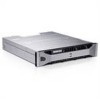
Dell™ PowerVault™ MD1200 and MD1220 Storage Enclosures Hardware Owner's Manual Regulatory Model: E03J Series and E04J Series Regulatory Type: E03J001 and E04J001 - Dell PowerVault MD1220 | Hardware Owner's Manual - Page 2
A CAUTION indicates potential damage to hardware or loss of data if instructions are not followed. WARNING: A WARNING indicates a potential for property Dell Inc. is strictly forbidden. Trademarks used in this text: Dell, the DELL logo, OpenManage, PowerEdge, and PowerVault are trademarks of Dell - Dell PowerVault MD1220 | Hardware Owner's Manual - Page 3
11 Back-Panel Features and Indicators 12 Enclosure Management Module 13 Enclosure Failover When Two EMMs are Installed 16 EMM Thermal Shutdown 16 Enclosure Alarms 16 Power Indicator Codes 17 Other Information You May Need 18 2 Operating Your Storage Enclosure . . . . . 19 Before You Begin 19 - Dell PowerVault MD1220 | Hardware Owner's Manual - Page 4
Downloading Firmware 26 3 Installing Enclosure Components . . . . . 27 Recommended Tools 27 Front Bezel (Optional 27 Removing the Front Bezel 27 Installing the Front Bezel 28 Hard Drives 29 Removing a Drive Blank 29 Installing a Drive Blank 31 Removing a Hard Drive 31 Installing a Hard - Dell PowerVault MD1220 | Hardware Owner's Manual - Page 5
50 Troubleshooting Enclosure Cooling Problems . . . . . 51 Troubleshooting Enclosure Management Modules. . . 52 Troubleshooting Hard Drives 53 Troubleshooting Enclosure Connections 54 Troubleshooting a Wet Enclosure 54 Troubleshooting a Damaged Enclosure 55 5 Getting Help 57 Contacting Dell 57 - Dell PowerVault MD1220 | Hardware Owner's Manual - Page 6
6 Contents - Dell PowerVault MD1220 | Hardware Owner's Manual - Page 7
About Your Enclosure Front-Panel Features and Indicators Figure 1-1. Front-Panel Features and Indicators-Dell™ PowerVault™ MD1200 1 2 3 4 5 6 Figure 1-2. Front-Panel Features and Indicators-Dell PowerVault MD1220 1 2 3 4 5 6 About Your Enclosure 7 - Dell PowerVault MD1220 | Hardware Owner's Manual - Page 8
at least one power supply is supplying power to the enclosure. The split mode LED lights when the enclosure is in a split-mode configuration. If the LED is not lit, it indicates that the enclosure is in a unified-mode configuration. The system identification button on the front control panel can - Dell PowerVault MD1220 | Hardware Owner's Manual - Page 9
to 12 3.5-inch SAS hot-swappable hard drives. PowerVault MD1220-Up to 24 2.5-inch SAS hot-swappable hard drives. When set in the top position, the enclosure is configured in unified mode. When set in the bottom position, the enclosure is configured in split mode. Front-Bezel Features and Indicators - Dell PowerVault MD1220 | Hardware Owner's Manual - Page 10
is turned on or is reset. Blinks amber when the enclosure is in the fault state. The power LED lights when at least one power supply is supplying power to the enclosure. The split mode LED lights when the enclosure is in a split-mode configuration. If the LED is not lit, it indicates that the - Dell PowerVault MD1220 | Hardware Owner's Manual - Page 11
status indicator (green and amber) Drive-Status Indicator Pattern (RAID Only) Condition Blinks green two times per second Identify drive/ initialized after system power is turned on. Drives are not ready for insertion or removal during this time. The Dell PowerEdge™ RAID controller PERC H800 - Dell PowerVault MD1220 | Hardware Owner's Manual - Page 12
Drive-Status Indicator Pattern (RAID Only) Condition Blinks green, amber, and off Icon Connector 1 Power supply/cooling PS 1 fan module 2 Primary enclosure EMM 0 management module (EMM) 3 Secondary EMM EMM 1 Description 600 W power supply. For more information, see "Power Indicator Codes" on - Dell PowerVault MD1220 | Hardware Owner's Manual - Page 13
temperature, fan, power supplies, and enclosure LEDs. • Controlling access to hard drives. • Communicating enclosure attributes and states to the host server. NOTE: At least one EMM must be installed in the enclosure. If only one EMM is installed in the enclosure, it must be installed in the primary - Dell PowerVault MD1220 | Hardware Owner's Manual - Page 14
are not connected. The LED remains off if enclosure is not connected. Provides SAS connections for cabling to the next down chain expansion enclosure in a daisy chain (unified mode only). NOTE: The SAS port Out is disabled if the enclosure is running in a split-mode configuration. 14 About Your - Dell PowerVault MD1220 | Hardware Owner's Manual - Page 15
is not connected. Lights green when the EMM is functioning properly. Lights amber when the enclosure does not boot or is not properly configured. Blinks green (On 250 ms* Off 250 ms) when a firmware download is in progress. Blinks green (On 1000 ms** Off 1000 ms) when a peer auto-update is in - Dell PowerVault MD1220 | Hardware Owner's Manual - Page 16
the EMM firmware or through a command from Dell™ OpenManage™ Server Administrator. Enclosure Alarms An audible alarm is activated if any of the fault conditions listed below occur. The alarm sounds continuously if: • More than one fan has failed or a power supply/cooling fan module is not installed - Dell PowerVault MD1220 | Hardware Owner's Manual - Page 17
setting in Server Administrator. For more information, see the Server Administrator documentation at support.dell.com/manuals. Power Indicator Codes Figure 1-7. Power Indicator Codes 1 2 3 Item LED Type 1 DC power Icon Description The LED lights green when the DC output voltage is within the - Dell PowerVault MD1220 | Hardware Owner's Manual - Page 18
documentation provides information about managing your storage solution using the storage management service within the server administrator. • The Dell PowerEdge RAID Controller (PERC) H700 and H800 User's Guide provides information about configuring RAID. • Any media that ships with your - Dell PowerVault MD1220 | Hardware Owner's Manual - Page 19
connecting your storage enclosure, ensure that the following are available: • Power cables • SAS cables • Rail kit • Dell Systems Management Tools and Documentation media • Documentation - Getting Started Guide - Rack Installation Instructions - Safety instructions Cabling Your Enclosure You can - Dell PowerVault MD1220 | Hardware Owner's Manual - Page 20
a split-mode configuration. Table 2-1. Split-Mode Configuration Enclosure EMM 0 Dell PowerVault MD1200 Drives 6 to 11 Dell PowerVault MD1220 Drives 12 to 23 EMM 1 Drives 0 to 5 Drives 0 to 11 NOTE: Clustering is not supported on PowerVault MD1200 and PowerVault M1220 enclosures. The operating - Dell PowerVault MD1220 | Hardware Owner's Manual - Page 21
the controller is properly installed. • If you are configuring your enclosure in a unified-mode configuration, connect the SAS cable from the host controller to the In port on the EMM module of the first enclosure in the daisy chain. See Figure 2-2. Attach subsequent storage enclosures in the daisy - Dell PowerVault MD1220 | Hardware Owner's Manual - Page 22
Figure 2-2. EMM Cabling Diagram in Unified Mode host controller 22 Operating Your Storage Enclosure - Dell PowerVault MD1220 | Hardware Owner's Manual - Page 23
Figure 2-3. EMM Cabling Diagram in Unified Mode (Redundant Path) host controller Operating Your Storage Enclosure 23 - Dell PowerVault MD1220 | Hardware Owner's Manual - Page 24
is in the OFF position. 6 Turn on the power switches on all power supply/cooling fan modules. 7 Turn on the host system. 8 Check the LED indicators on the front and back panel of the storage enclosure. If any of the LEDs are amber, see "Troubleshooting Your Enclosure" on page 49. 24 Operating Your - Dell PowerVault MD1220 | Hardware Owner's Manual - Page 25
-mode configurations do not support daisy-chaining of enclosures and redundant paths. 3 Turn off the host system. 4 Turn off the enclosure by turning off both power supply/cooling fan modules. 5 Change the position of the enclosure mode switch. 6 Rearrange the disks in the enclosure as necessary - Dell PowerVault MD1220 | Hardware Owner's Manual - Page 26
RAID storage configurations • display storage information • customize event reporting • view logged events For more information, see the Server Administrator documentation at support.dell.com/manuals. Downloading Firmware You can download firmware updates for your storage enclosure using the Dell - Dell PowerVault MD1220 | Hardware Owner's Manual - Page 27
Installing Enclosure Components Recommended Tools You may need the following items to perform the procedures in this section: • Key to the system keylock • #2 Phillips screwdriver • Wrist grounding strap Front Bezel (Optional) Removing the Front Bezel 1 Using the system key, unlock the front bezel ( - Dell PowerVault MD1220 | Hardware Owner's Manual - Page 28
and Installing the Front Bezel 1 2 3 4 1 bezel 3 release latch 2 keylock 4 hinge tab Installing the Front Bezel 1 Hook the right end of the bezel onto the chassis. 2 Fit the free end of the bezel onto the system. 3 Secure the bezel with the keylock. See Figure 3-1. 28 Installing Enclosure - Dell PowerVault MD1220 | Hardware Owner's Manual - Page 29
blanks installed. 1 If installed, remove the front bezel. See "Removing the Front Bezel" on page 27. 2 Press the release tab and slide the drive blank out until it is free of the drive bay. See Figure 3-2 for PowerVault MD1200 and Figure 3-3 for PowerVault MD1220. Installing Enclosure Components - Dell PowerVault MD1220 | Hardware Owner's Manual - Page 30
Figure 3-2. Removing and Installing a 3.5-Inch Hard-Drive Blank 1 2 1 drive blank 2 release tab Figure 3-3. Removing and Installing a 2.5-Inch Hard-Drive Blank 1 2 1 drive blank 2 release tab 30 Installing Enclosure Components - Dell PowerVault MD1220 | Hardware Owner's Manual - Page 31
should only perform troubleshooting and simple repairs as authorized in your product documentation, or as directed by the online or telephone service and support team. Damage due to servicing that is not authorized by Dell is not covered by your warranty. Read and follow the safety instructions that - Dell PowerVault MD1220 | Hardware Owner's Manual - Page 32
should only perform troubleshooting and simple repairs as authorized in your product documentation, or as directed by the online or telephone service and support team. Damage due to servicing that is not authorized by Dell is not covered by your warranty. Read and follow the safety instructions that - Dell PowerVault MD1220 | Hardware Owner's Manual - Page 33
screws from the slide rails on the hard-drive carrier and separate the hard drive from the carrier. See Figure 3-5 for PowerVault MD1200 and Figure 3-6 for PowerVault MD1220. Figure 3-5. Removing and Installing a Hard Drive Into a 3.5-Inch Drive Carrier 4 1 3 2 Installing Enclosure Components 33 - Dell PowerVault MD1220 | Hardware Owner's Manual - Page 34
1 screws (4) 3 SAS screw hole 2 drive carrier 4 hard drive Figure 3-6. Removing and Installing a Hard Drive Into a 2.5-Inch Drive Carrier 4 1 3 2 1 screws (4) 3 SAS screw hole 2 drive carrier 4 hard drive 34 Installing Enclosure Components - Dell PowerVault MD1220 | Hardware Owner's Manual - Page 35
modules (EMM) and can be configured in either unified mode or split mode. An enclosure with non-redundant enclosure management consists of only one EMM in unified mode. If only one EMM is installed in your enclosure, it must be installed in EMM 0. You must install the EMM blank in EMM 1. CAUTION - Dell PowerVault MD1220 | Hardware Owner's Manual - Page 36
6 Connect all the power cables to the enclosure. 7 Turn on the enclosure and the host server. Figure 3-7. Removing and Installing an EMM Blank 12 1 release latch 2 EMM blank Installing an EMM Blank To install an EMM blank, align the blank with the EMM bay and insert the blank into the chassis - Dell PowerVault MD1220 | Hardware Owner's Manual - Page 37
should only perform troubleshooting and simple repairs as authorized in your product documentation, or as directed by the online or telephone service and support team. Damage due to servicing that is not authorized by Dell is not covered by your warranty. Read and follow the safety instructions that - Dell PowerVault MD1220 | Hardware Owner's Manual - Page 38
Figure 3-8. Removing and Installing an EMM 3 2 1 1 EMM 3 release lever 2 release tab 38 Installing Enclosure Components - Dell PowerVault MD1220 | Hardware Owner's Manual - Page 39
should only perform troubleshooting and simple repairs as authorized in your product documentation, or as directed by the online or telephone service and support team. Damage due to servicing that is not authorized by Dell is not covered by your warranty. Read and follow the safety instructions that - Dell PowerVault MD1220 | Hardware Owner's Manual - Page 40
are heavy. Use both hands while removing the module. 4 Press the release tab and pull the power supply out of the chassis. Figure 3-9. Removing and Installing a Power Supply/Cooling Fan Module OUT OUT 1 2 1 power supply 3 power supply handle 3 2 release tab 40 Installing Enclosure Components - Dell PowerVault MD1220 | Hardware Owner's Manual - Page 41
cable with the Velcro strap. NOTE: If the enclosure is powered on, all the power supply LEDs remain off until the AC power cable is connected to the power supply/cooling fan module and the power switch is turned on. 4 Turn on the power supply/cooling fan module. Installing Enclosure Components 41 - Dell PowerVault MD1220 | Hardware Owner's Manual - Page 42
remove it. 4 Slide the control panel out of the chassis after: - Pushing the release tab toward the front of the enclosure in PowerVault MD1200. See Figure 3-11. - Pulling the release pin toward the front of the enclosure in PowerVault MD1220. See Figure 3-12. 42 Installing Enclosure Components - Dell PowerVault MD1220 | Hardware Owner's Manual - Page 43
Figure 3-11. Removing and Installing the Control Panel-PowerVault MD1200 1 2 1 control panel 2 release tab Figure 3-12. Removing and Installing the Control Panel-PowerVault MD1220 2 1 1 control panel 2 release pin Installing Enclosure Components 43 - Dell PowerVault MD1220 | Hardware Owner's Manual - Page 44
should only perform troubleshooting and simple repairs as authorized in your product documentation, or as directed by the online or telephone service and support team. Damage due to servicing that is not authorized by Dell is not covered by your warranty. Read and follow the safety instructions that - Dell PowerVault MD1220 | Hardware Owner's Manual - Page 45
the screws that secure the backplane and pull the backplane out of the enclosure. See Figure 3-14 for PowerVault MD1200 or Figure 3-15 for PowerVault MD1220. Figure 3-13. Removing and Installing the EMM/Power Supply Cage 2 1 EMM/power supply cage 1 2 screws (6) Installing Enclosure Components 45 - Dell PowerVault MD1220 | Hardware Owner's Manual - Page 46
Figure 3-14. Removing and Installing the Backplane-PowerVault MD1200 1 2 3 1 screws (5) 3 captive screw 2 backplane Figure 3-15. Removing and Installing the Backplane-PowerVault MD1220 1 2 3 1 screws (4) 3 captive screw 2 backplane 46 Installing Enclosure Components - Dell PowerVault MD1220 | Hardware Owner's Manual - Page 47
PowerVault MD1220. 4 Align the slots on the EMM/power supply cage with the tabs on the chassis. See Figure 3-13. 5 Push the EMM/power supply cage toward the front of the enclosure. 6 Replace the screws that secure the EMM/power supply cage to the chassis. 7 Replace the control panel. See "Installing - Dell PowerVault MD1220 | Hardware Owner's Manual - Page 48
48 Installing Enclosure Components - Dell PowerVault MD1220 | Hardware Owner's Manual - Page 49
product documentation, or as directed by the online or telephone service and support team. Damage due to servicing that is not authorized by Dell is not covered by your warranty. Read and follow the safety instructions that came with the product. Troubleshooting Enclosure Startup Failure If your - Dell PowerVault MD1220 | Hardware Owner's Manual - Page 50
should only perform troubleshooting and simple repairs as authorized in your product documentation, or as directed by the online or telephone service and support team. Damage due to servicing that is not authorized by Dell is not covered by your warranty. Read and follow the safety instructions that - Dell PowerVault MD1220 | Hardware Owner's Manual - Page 51
the enclosure is powered on, you must update the firmware. For information about updating the firmware, see "Downloading Firmware" on page 26. Troubleshooting Enclosure Cooling Problems CAUTION: Many repairs may only be done by a certified service technician. You should only perform troubleshooting - Dell PowerVault MD1220 | Hardware Owner's Manual - Page 52
should only perform troubleshooting and simple repairs as authorized in your product documentation, or as directed by the online or telephone service and support team. Damage due to servicing that is not authorized by Dell is not covered by your warranty. Read and follow the safety instructions that - Dell PowerVault MD1220 | Hardware Owner's Manual - Page 53
should only perform troubleshooting and simple repairs as authorized in your product documentation, or as directed by the online or telephone service and support team. Damage due to servicing that is not authorized by Dell is not covered by your warranty. Read and follow the safety instructions that - Dell PowerVault MD1220 | Hardware Owner's Manual - Page 54
should only perform troubleshooting and simple repairs as authorized in your product documentation, or as directed by the online or telephone service and support team. Damage due to servicing that is not authorized by Dell is not covered by your warranty. Read and follow the safety instructions that - Dell PowerVault MD1220 | Hardware Owner's Manual - Page 55
should only perform troubleshooting and simple repairs as authorized in your product documentation, or as directed by the online or telephone service and support team. Damage due to servicing that is not authorized by Dell is not covered by your warranty. Read and follow the safety instructions that - Dell PowerVault MD1220 | Hardware Owner's Manual - Page 56
56 Troubleshooting Your Enclosure - Dell PowerVault MD1220 | Hardware Owner's Manual - Page 57
, or Dell product catalog. Dell provides several online and telephone-based support and service options. Availability varies by country and product, and some services may not be available in your area. To contact Dell for sales, technical support, or customer service issues: 1 Visit support.dell.com - Dell PowerVault MD1220 | Hardware Owner's Manual - Page 58
58 Getting Help - Dell PowerVault MD1220 | Hardware Owner's Manual - Page 59
- Advanced Configuration and Power Interface. A standard interface for enabling the operating system to direct configuration and power management. ambient and RAM. C - Celsius. cache - A fast storage area that keeps a copy of data or instructions for quick data retrieval. cm - Centimeter(s). COMn - - Dell PowerVault MD1220 | Hardware Owner's Manual - Page 60
- Direct current a peripheral. DHCP - Dynamic Host Configuration Protocol. A method of automatically assigning remote access. ERA allows you to perform remote, or "out-ofband," server management DOS to organize and keep track of file storage. The Microsoft® Windows® operating systems can optionally - Dell PowerVault MD1220 | Hardware Owner's Manual - Page 61
a storage device. hot-plug - The ability to insert or install a device, typically a hard drive or an internal cooling fan, into the host system while the system is powered storage devices. iDRAC - Internet Dell cannot operate both devices simultaneously. iSCSI - Internet SCSI (see SCSI - Dell PowerVault MD1220 | Hardware Owner's Manual - Page 62
Plastic plugs containing a wire fit down over the pins. The wire connects the pins and creates a circuit, providing a simple and reversible method of changing the circuitry in a board. K - Kilo-; 1000. Kb - Kilobit(s); 1024 bits. KB - Kilobyte(s); 1024 bytes. Kbps - Kilobit(s) per second. KBps - - Dell PowerVault MD1220 | Hardware Owner's Manual - Page 63
Attached Storage. NAS is one of the concepts used for implementing shared storage on a network. NAS systems have their own operating systems, integrated hardware, and software that are optimized to serve specific storage needs. NIC - Network interface controller. A device that is installed or - Dell PowerVault MD1220 | Hardware Owner's Manual - Page 64
and the POST. ROMB - RAID on motherboard. SAN - Storage Area Network. A network architecture that enables remote networkattached storage devices to appear to a server to be locally attached. SAS - Serial-attached SCSI. SATA - Serial Advanced Technology Attachment. A standard interface between the - Dell PowerVault MD1220 | Hardware Owner's Manual - Page 65
to the system. service tag - A bar code label on the system used to identify it when you call Dell for technical support. SMART - Self- installed and how the system should be configured for operation. system memory - See RAM. System Setup program - A BIOS-based program that allows you to configure - Dell PowerVault MD1220 | Hardware Owner's Manual - Page 66
changing settings in the configuration software for the power supply. A battery-powered unit that automatically supplies power disk drives, or printers, for example. V - Volt(s). VAC - Volt(s) alternating current. VDC - Volt(s) direct install the appropriate video drivers and your monitor must support - Dell PowerVault MD1220 | Hardware Owner's Manual - Page 67
WH - Watt-hour(s). XML - Extensible Markup Language. XML is a way to create common information formats and to share both the format and the data on the World Wide Web, intranets, and elsewhere. ZIF - Zero insertion force. Glossary 67 - Dell PowerVault MD1220 | Hardware Owner's Manual - Page 68
68 Glossary - Dell PowerVault MD1220 | Hardware Owner's Manual - Page 69
mode, 20 contacting Dell, 57 control panel installing, 44 removing, 42 D Dell contacting, 57 drive carrier hard drive, 33 E enclosure managing, 26 enclosure mode cabling, 19 changing, 25 split, 19 unified, 19 F firmware downloading, 26 front bezel installing, 28 removing, 27 front panel features - Dell PowerVault MD1220 | Hardware Owner's Manual - Page 70
blank, 35 front bezel, 27 hard drive, 31 hard drive from a drive carrier, 33 power supply/cooling fan module, 39 S safety, 49 support contacting Dell, 57 T telephone numbers, 57 thermal shutdown, 16 troubleshooting, 49 connections, 54 cooling problems, 51 damaged enclosure, 55 external connections
-
 1
1 -
 2
2 -
 3
3 -
 4
4 -
 5
5 -
 6
6 -
 7
7 -
8
-
9
-
10
-
11
-
12
-
13
-
14
-
15
-
16
-
17
-
18
-
19
-
20
-
21
-
22
-
23
-
24
-
25
-
26
-
27
-
28
-
29
-
30
-
31
-
32
-
33
-
34
-
35
-
36
-
37
-
38
-
39
-
40
-
41
-
42
-
43
-
44
-
45
-
46
-
47
-
48
-
49
-
50
-
51
-
52
-
53
-
54
-
55
-
56
-
57
-
58
-
59
-
60
-
61
-
62
-
63
-
64
-
65
-
66
-
67
-
68
-
69
-
70
 |
 |

Dell™ PowerVault™
MD1200 and MD1220
Storage Enclosures
Hardware Owner’s
Manual
Regulatory Model: E03J Series and E04J Series
Regulatory Type: E03J001 and E04J001