Dell PowerVault TL2000 Dell Model TL2000/TL4000 Tape Library- User's Guide - Page 205
Con Logical Libraries, Con Library, Logical, Libraries
 |
View all Dell PowerVault TL2000 manuals
Add to My Manuals
Save this manual to your list of manuals |
Page 205 highlights
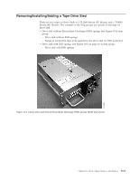
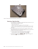
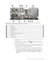
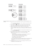
7 9 10 4 7 a77ug204 6 1 3 285 Figure 10-6. Drive sled components (full-high fibre drive in top position, half-high SCSI drive in middle position, half-high SAS drive in bottom position) on back panel of a 4U library 1 SCSI cable 2 SAS cable 3 SCSI terminator 4 Fibre Channel cable 5 Ethernet cable 6 Power cords 7 Drive sled blue captive thumbscrews 8 Black pull-out tab 9 Drive sled 10 Drive sled handle 5. If present, remove the conductive tape from the drive sled (refer to Figure 10-9 on page 10-8). 6. Loosen the blue captive thumbscrews ( 7 in Figure 10-6) on the drive sled. 7. Pull straight back on the drive sled handle ( 10 ) to remove it from the library (see Figure 10-7 on page 10-6). 8. If you are replacing the tape drive sled, proceed to Installing a Tape Drive Sled for instructions. If you are not replacing the tape drive sled immediately, you will need to perform the following procedures: a. Install a drive cover plate to protect your library from dust and debris. b. To remove the "Missing drive" indicators on the Operator Control Panel (Attention LED) and the Web User Interface (System Status screen), modify or resubmit logical library setting (Operator Control Panel: Configure → Logical Libraries or Web User Interface: Configure Library → Logical Libraries). Chapter 10. Check, Adjust, Remove, and Replace 10-5
-
 1
1 -
2
-
3
-
4
-
5
-
6
-
7
-
8
-
9
-
10
-
11
-
12
-
13
-
14
-
15
-
16
-
17
-
18
-
19
-
20
-
21
-
22
-
23
-
24
-
25
-
26
-
27
-
28
-
29
-
30
-
31
-
32
-
33
-
34
-
35
-
36
-
37
-
38
-
39
-
40
-
41
-
42
-
43
-
44
-
45
-
46
-
47
-
48
-
49
-
50
-
51
-
52
-
53
-
54
-
55
-
56
-
57
-
58
-
59
-
60
-
61
-
62
-
63
-
64
-
65
-
66
-
67
-
68
-
69
-
70
-
71
-
72
-
73
-
74
-
75
-
76
-
77
-
78
-
79
-
80
-
81
-
82
-
83
-
84
-
85
-
86
-
87
-
88
-
89
-
90
-
91
-
92
-
93
-
94
-
95
-
96
-
97
-
98
-
99
-
100
-
101
-
102
-
103
-
104
-
105
-
106
-
107
-
108
-
109
-
110
-
111
-
112
-
113
-
114
-
115
-
116
-
117
-
118
-
119
-
120
-
121
-
122
-
123
-
124
-
125
-
126
-
127
-
128
-
129
-
130
-
131
-
132
-
133
-
134
-
135
-
136
-
137
-
138
-
139
-
140
-
141
-
142
-
143
-
144
-
145
-
146
-
147
-
148
-
149
-
150
-
151
-
152
-
153
-
154
-
155
-
156
-
157
-
158
-
159
-
160
-
161
-
162
-
163
-
164
-
165
-
166
-
167
-
168
-
169
-
170
-
171
-
172
-
173
-
174
-
175
-
176
-
177
-
178
-
179
-
180
-
181
-
182
-
183
-
184
-
185
-
186
-
187
-
188
-
189
-
190
-
191
-
192
-
193
-
194
-
195
-
196
-
197
-
198
-
199
-
 200
200 -
 201
201 -
 202
202 -
 203
203 -
 204
204 -
 205
205 -
 206
206 -
 207
207 -
 208
208 -
 209
209 -
 210
210 -
211
-
212
-
213
-
214
-
215
-
216
-
217
-
218
-
219
-
220
-
221
-
222
-
223
-
224
-
225
-
226
-
227
-
228
-
229
-
230
-
231
-
232
-
233
-
234
-
235
-
236
-
237
-
238
-
239
-
240
-
241
-
242
-
243
-
244
-
245
-
246
-
247
-
248
-
249
-
250
-
251
-
252
-
253
-
254
-
255
-
256
-
257
-
258
-
259
-
260
-
261
-
262
-
263
-
264
-
265
-
266
-
267
-
268
-
269
-
270
-
271
-
272
-
273
-
274
-
275
-
276
-
277
-
278
-
279
-
280
-
281
-
282
-
283
 |
 |
