Dell S5224F-ON EMC PowerSwitch S5200F-ON Series Installation Guide February 20 - Page 50
Fan module installation, Fan LEDs
 |
View all Dell S5224F-ON manuals
Add to My Manuals
Save this manual to your list of manuals |
Page 50 highlights
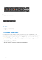
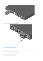
1. Fans The S5212F-ON switch fan modules: 1. Fans Fan LEDs ● Solid green-Fan function is normal. ● Flashing yellow-There is a fan fault. ● Off-Fan is off. Fan module installation For all switches except the S5212F-ON, the fan modules in the S5200F-ON Series switch are field replaceable. For the S5212F-ON switch, the fans are fixed. For the S5224F-ON, S5232F-ON, and S5248F-ON switches, fan module slots 1 and 2 are on the left side of the switch and fan module slots 3 and 4 are on the right side of the switch. For the S5296F-ON switch, fan module slots 1 through 4 are on the left side of the switch. For the S5212F-ON switch, the fans are across the entire switch. CAUTION: DO NOT mix airflow directions. All fans must use the same airflow direction-reverse or normal. If you mix the airflow direction, to avoid damage to the switch, you must correct the mixed airflow. 1. Take the fan module out of the shipping box. 2. Slide the module into the bay. The S5224F-ON, S5232F-ON, or S5248F-ON switch fan module installation: 50 Fans
-
 1
1 -
2
-
3
-
4
-
5
-
6
-
7
-
8
-
9
-
10
-
11
-
12
-
13
-
14
-
15
-
16
-
17
-
18
-
19
-
20
-
21
-
22
-
23
-
24
-
25
-
26
-
27
-
28
-
29
-
30
-
31
-
32
-
33
-
34
-
35
-
36
-
37
-
38
-
39
-
40
-
41
-
42
-
43
-
44
-
 45
45 -
 46
46 -
 47
47 -
 48
48 -
 49
49 -
 50
50 -
 51
51 -
 52
52 -
 53
53 -
 54
54 -
 55
55 -
56
-
57
-
58
-
59
-
60
-
61
-
62
-
63
-
64
 |
 |
