Dell S5248F-ON EMC SmartFabric OS10 Switch Configuration Guide for VxRail 4.7 - Page 26
S5248F-Leaf1A, S5248F-Leaf1B, VxRail node 1, VxRail node 2, VxRail node 3, VxRail node 4
 |
View all Dell S5248F-ON manuals
Add to My Manuals
Save this manual to your list of manuals |
Page 26 highlights
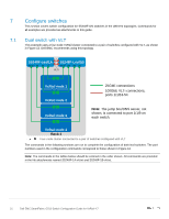
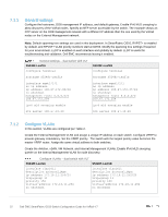
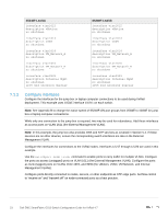
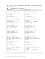
7.2 Dual switch without VLT This example uses a four-node VxRail cluster connected to a switch pair without VLT, as shown in Figure 13. S5248F-Leaf1A 1/1/20 19 18 17 S5248F-Leaf1B 1/1/17 18 19 20 LACP VxRail node 1 VxRail node 2 VxRail node 3 25GbE connections 100GbE LACP connections, ports 1/1/53-54 Note: The jump box/DNS server, not shown, is connected to port 1/1/9 on each switch. VxRail node 4 Rack 1 Four-node cluster connected to a switch pair without VLT In this topology, an LACP port channel is used to connect the two switches. The commands in the following sections are run to complete the configuration of both switches. The port numbers used in the configuration commands correspond to those shown in Figure 13. Note: The commands in the tables below should be entered in the order shown. All commands are provided in the file attachments named S5248F-1A-no-vlt.txt and S5248F-1B-no-vlt.txt. 26 Dell EMC SmartFabric OS10 Switch Configuration Guide for VxRail 4.7
-
 1
1 -
2
-
3
-
4
-
5
-
6
-
7
-
8
-
9
-
10
-
11
-
12
-
13
-
14
-
15
-
16
-
17
-
18
-
19
-
20
-
 21
21 -
 22
22 -
 23
23 -
 24
24 -
 25
25 -
 26
26 -
 27
27 -
 28
28 -
 29
29 -
 30
30 -
 31
31 -
32
-
33
-
34
-
35
-
36
-
37
-
38
-
39
-
40
-
41
-
42
-
43
-
44
-
45
-
46
-
47
-
48
-
49
 |
 |
