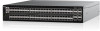
Dell S5296F-ON EMC PowerSwitch S5200F-ON Series Setup Guide - Page 14
Two-post flush-mount installation, Two-post center-mount installation
 |
View all Dell S5296F-ON manuals
Add to My Manuals
Save this manual to your list of manuals |
Page 14 highlights
2. Align and seat the front flange pegs in the holes on the front side of the vertical post. NOTE: Be sure that the rails click into place and are secure. 3. Repeat this procedure for the second rail. To remove each rail, pull on the latch release button on each flange ear and unseat each rail. Two-post flush-mount installation NOTE: For more installation instructions, see the installation labels attached to the rail assembly. 1. For this configuration, remove the latch castings from the front side of each ReadyRails assembly, item 1. To remove the two screws from each front flange ear on the switch side of the rail and remove each latch casting, use a Torx screwdriver. Retain the latch castings for future rack requirements. It is not necessary to remove the back flange castings. Figure 13. Two-post flush-mount installation 2. Attach one rail to the front post flange with two user-supplied screws, item 2. 3. Slide the plunger bracket forward against the vertical post and secure the plunger bracket to the post flange with two user-supplied screws, item 3. 4. Repeat this procedure for the second rail. Two-post center-mount installation NOTE: For more installation instructions, see the installation labels attached to the rail assembly. 1. Slide the plunger bracket rearward until it clicks into place and secure the bracket to the front post flange with two user-supplied screws, item 1. 14 S5200F-ON Series switch Installation
-
 1
1 -
2
-
3
-
4
-
5
-
6
-
7
-
8
-
 9
9 -
 10
10 -
 11
11 -
 12
12 -
 13
13 -
 14
14 -
 15
15 -
 16
16 -
 17
17 -
 18
18 -
 19
19 -
20
-
21
-
22
-
23
-
24
-
25
-
26
 |
 |
