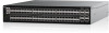
Dell S5296F-ON EMC PowerSwitch S5200F-ON Series Setup Guide - Page 9
Ground cable, Rack or cabinet installation, Rack mount safety considerations
 |
View all Dell S5296F-ON manuals
Add to My Manuals
Save this manual to your list of manuals |
Page 9 highlights
Ground cable To attach a ground cable to the switch, use the included M4 screws. NOTE: For an AC-powered switch, although the third conductor of the AC power cable provides a ground path, Dell EMC recommends grounding your switch with a dedicated ground wire. You can order an AC ground lug separately. NOTE: For a DC-powered switch, the only way to safely ground your switch is to attach a dedicated ground wire. The ground lug kit ships in a plastic bag placed with the other accessories inside the shipping box. The ground lug bracket screws ship attached to the switch. Before you install the DC switch in the dual-tray, attach the ground lug and bracket to the switch using the included screws and then attach the DC ground wire to the ground lug. The ground cable is not included. The grounding lugs must be a UL-recognized, crimp-type lug. CAUTION: Grounding conductors must be made of copper. Do not use aluminum conductors. NOTE: Coat the one-hole lug with an anti-oxidant compound before crimping. Also, bring any unplated mating surfaces to a shiny finish and coat with an anti-oxidant before mating. Plated mating surfaces must be clean and free from contamination. NOTE: The rack installation ears are not suitable for grounding. To connect the ground cable to the switch: 1. Cut the user-supplied ground cable to the wanted length. The cable length must facilitate proper operation of the fault interrupt circuits. Use the shortest cable route allowable. 2. Crimp the ground cable inside the pre-installed ground lug. 3. Attach the other end of the ground cable to a suitable ground point such as the rack or cabinet. The rack installation ears are not a suitable grounding point. Rack or cabinet installation You may either place the switch on a rack shelf or mount the switch directly into a 19" wide, EIA-310- E-compliant rack. Rack mounting for the S5232F-ON, S5248F-ON, and S5224F-ON switches includes four-post, two-post, round threaded holes, or square holes. The ReadyRails system is provided for 1U front-rack and two-post installations. Do not use the ReadyRails system for the S5296F-ON or S5212F-ON switches. For the S5296F-ON switch, see Two U four-post rack assembly. For the S5212F-ON switch, see One-half U front-rack installation. The ReadyRails system includes two separately packaged rail assemblies. To begin installation, separate each rail assembly by sliding the inside rail out of the outside rail. WARNING: This guide is a condensed reference. Read the safety instructions in your Safety, Environmental, and Regulatory information booklet before you begin. NOTE: The illustrations in this section are not intended to represent a specific switch. NOTE: Do not the use the mounted ReadyRails as a shelf or a workplace. Rack mount safety considerations • Rack loading-Overloading or uneven loading of racks may result in shelf or rack failure, possibly damaging the equipment and causing personal injury. Stabilize racks in a permanent location before loading begins. Mount the components starting at the bottom of the rack, then work to the top. Do not exceed your rack's load rating. • Power considerations-Connect only to the power source specified on the unit. When you install multiple electrical components in a rack, ensure that the total component power ratings do not exceed the circuit capabilities. Overloaded power sources and extension cables are fire and shock hazards. • Elevated ambient temperature-If you install the switch in a closed rack assembly, the operating temperature of the rack environment may be greater than the room ambient temperature. Use care not to exceed the 45°C (113°F) maximum ambient temperature of the switch. S5200F-ON Series switch Installation 9
-
 1
1 -
2
-
3
-
 4
4 -
 5
5 -
 6
6 -
 7
7 -
 8
8 -
 9
9 -
 10
10 -
 11
11 -
 12
12 -
 13
13 -
 14
14 -
15
-
16
-
17
-
18
-
19
-
20
-
21
-
22
-
23
-
24
-
25
-
26
 |
 |
