Dell S5296F-ON EMC PowerSwitch S5200F-ON Series Setup Guide - Page 8
S5200F-ON Series switch Installation, Unpack
 |
View all Dell S5296F-ON manuals
Add to My Manuals
Save this manual to your list of manuals |
Page 8 highlights
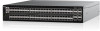
3 S5200F-ON Series switch Installation To install the S5200F-ON Series (S5232F-ON, S5248F-ON, S5296F-ON, S5224F-ON, and S5212F-ON) switch, complete the installation procedures in the order presented in this section. Always handle the switch and its components with care. Avoid dropping the switch or any field replaceable units (FRUs). NOTE: ESD damage can occur if components are mishandled. Always wear an ESD-preventive wrist or heel ground strap when handling the switch and its components. As with all electrical devices of this type, take all the necessary safety precautions to prevent injury when installing this switch. Topics: • Unpack • Ground cable • Rack or cabinet installation • One-half U front-rack installation • One U ReadyRails installation • Two U four-post rack assembly • DC power connections • S5212F-ON only DC power connections • Optics installation • Switch start up • After switch installation Unpack NOTE: Before unpacking the switch, inspect the container and immediately report any evidence of damage. NOTE: For the S5212F-ON and S5296F-ON switches only: the USB extension cable is packaged separately. Do not throw it away. When unpacking the switch, ensure that the following items are included: • One S5200F-ON Series switch • Two sets of rail kits, no tools needed • One RJ-45 to DB-9 female cable • S5232F-ON, S5248F-ON, S5296F-ON, and S5224F-ON: Two hot-swappable PSUs • S5232F-ON, S5248F-ON, S5296F-ON, and S5224F-ON: Four hot-swappable fan units • S5212F-ON: Two fixed PSUs • S5212F-ON: one USB extension cable; male to female • S5212F-ON: Two fixed fan units • S5296F-ON: one USB extension cable; male to female • DC switches only: DC power ground lug kit • Two country- and region-specific AC power cables and wire clips • S5200F-ON Series Set-up Guide • Safety and Regulatory Information • Warranty and Support Information 1. Place the container on a clean, flat surface and cut all straps securing the container. 2. Open the container, or remove the container top. 3. Carefully remove the switch from the container and place it on a secure and clean surface. 4. Remove all packing material. 5. Inspect the product and accessories for damage. 8 S5200F-ON Series switch Installation
-
 1
1 -
2
-
 3
3 -
 4
4 -
 5
5 -
 6
6 -
 7
7 -
 8
8 -
 9
9 -
 10
10 -
 11
11 -
 12
12 -
 13
13 -
14
-
15
-
16
-
17
-
18
-
19
-
20
-
21
-
22
-
23
-
24
-
25
-
26
 |
 |
