Dell XPS 13 9310 Service Manual - Page 8
Removing and installing components, Recommended tools, Screw list
 |
View all Dell XPS 13 9310 manuals
Add to My Manuals
Save this manual to your list of manuals |
Page 8 highlights
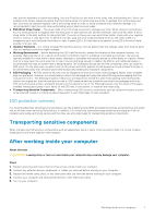
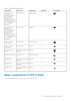
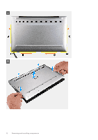
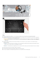
2 Removing and installing components NOTE: The images in this document may differ from your computer depending on the configuration you ordered. Recommended tools The procedures in this document may require the following tools: ● Phillips screwdriver #0 ● Phillips screwdriver #1 ● Torx #5 (T5) screwdriver ● Plastic scribe Screw list NOTE: When removing screws from a component, it is recommended to note the screw type, the quantity of screws, and then place them in a screw storage box. This is to ensure that the correct number of screws and correct screw type is restored when the component is replaced. NOTE: Some computers have magnetic surfaces. Ensure that the screws are not left attached to such surfaces when replacing a component. NOTE: Screw color may vary with the configuration ordered. Table 1. Screw list Component Secured to Screw type Base cover Palm-rest and keyboard M2x3, Torx 5 assembly Quantity 8 Screw image Battery Palm-rest and keyboard M1.6x2.5 5 assembly Solid-state drive shield System board M2x3 1 Fans (in computers shipped with computers shipped with 11th Generation Intel Core i3-1115G4 processor) System board Heat sink (in computers shipped with computers shipped with 11th Generation Intel Core i3-1115G4 processor) System board M1.6x2.5 4 M2x3 (captive) 4 8 Removing and installing components
-
 1
1 -
2
-
 3
3 -
 4
4 -
 5
5 -
 6
6 -
 7
7 -
 8
8 -
 9
9 -
 10
10 -
 11
11 -
 12
12 -
 13
13 -
14
-
15
-
16
-
17
-
18
-
19
-
20
-
21
-
22
-
23
-
24
-
25
-
26
-
27
-
28
-
29
-
30
-
31
-
32
-
33
-
34
-
35
-
36
-
37
-
38
-
39
-
40
-
41
-
42
-
43
-
44
-
45
-
46
-
47
-
48
-
49
-
50
-
51
-
52
-
53
-
54
-
55
-
56
-
57
-
58
-
59
-
60
-
61
 |
 |
