Dell XPS 13 9365 2-in-1 XPS 13 Convertible Service Manual - Page 28
Replacing the display assembly, Procedure, Post-requisites
 |
View all Dell XPS 13 9365 2-in-1 manuals
Add to My Manuals
Save this manual to your list of manuals |
Page 28 highlights
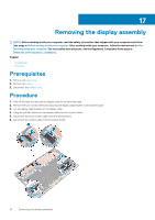
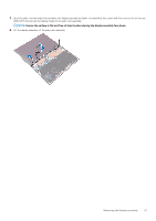
18 Replacing the display assembly NOTE: Before working inside your computer, read the safety information that shipped with your computer and follow the steps in Before working inside your computer. After working inside your computer, follow the instructions in After working inside your computer. For more safety best practices, see the Regulatory Compliance home page at www.dell.com/regulatory_compliance. Topics: • Procedure • Post-requisites Procedure 1. Slide the palm-rest assembly under the display hinges and align the screw holes on the palm-rest assembly with the screw holes on the display hinges. 2. Replace the six screws (M2.5x3.5) that secure the palm-rest assembly to the display hinges. 3. Close the palm-rest assembly. 4. Connect the display cable to the system board. 5. Align the screw holes on the display-cable bracket with the screw holes on the system board. 6. Replace the two screws (M1.6x2.5) that secure the display-cable bracket to the system board. 7. Adhere the display cable tape to the system board. 8. Connect the touch-screen cable and camera cable to the system board. Post-requisites 1. Reconnect the wireless card. 2. Replace the battery. 3. Replace the base cover. 28 Replacing the display assembly
-
 1
1 -
2
-
3
-
4
-
5
-
6
-
7
-
8
-
9
-
10
-
11
-
12
-
13
-
14
-
15
-
16
-
17
-
18
-
19
-
20
-
21
-
22
-
 23
23 -
 24
24 -
 25
25 -
 26
26 -
 27
27 -
 28
28 -
 29
29 -
 30
30 -
 31
31 -
 32
32 -
 33
33 -
34
-
35
-
36
-
37
-
38
-
39
-
40
-
41
-
42
-
43
-
44
-
45
-
46
-
47
-
48
-
49
 |
 |
