Denon ADV-1000 Owners Manual - Page 9
Connecting video components - instructions
 |
View all Denon ADV-1000 manuals
Add to My Manuals
Save this manual to your list of manuals |
Page 9 highlights
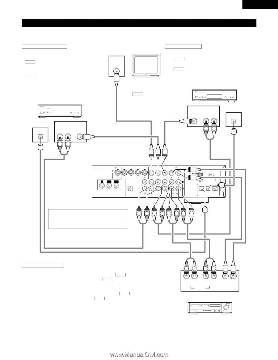
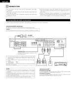
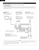
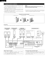
ENGLISH (2) Connecting video components • To connect the video signal, connect using a 75 Ω/ohms video signal cable cord. Using an improper cable can result in a drop in video quality. • When making connections, also refer to the operating instructions of the other components. Connecting a TV/DBS tuner TV/DBS • Connect the TV's or DBS tuner's video output jack (VIDEO OUTPUT) to the VIDEO (yellow) TV/DBS IN jack using a 75 Ω/ohms video coaxial pin plug cord. • Connect the TV's or DBS tuner's audio output jacks (AUDIO OUTPUT) to the AUDIO TV/DBS IN jacks using pin plug cords. • For devices with optical digital outputs, connect the digital output terminal to the ADV-1000's DIGITAL TV/DBS IN terminal using an optical transmission cable. TV or DBS tuner B OPTICAL OUT AUDIO OUT RL VIDEO OUT Connecting a CS tuner Monitor TV V.AUX • Connect the CS tuner's video output jack (VIDEO OUTPUT) to VIDEO IN the VIDEO (yellow) V.AUX IN jack using a 75 Ω/ohms video coaxial pin plug cord. • Connect the CS tuner's audio output jacks (AUDIO OUTPUT) to the AUDIO V.AUX IN jacks using pin plug cords. • For devices with optical digital outputs, connect the digital output terminal to the ADV-1000's DIGITAL V.AUX. IN terminal using an optical transmission cable. MONITOR OUT • Connect the TV's video CS tuner input jack (VIDEO INPUT) to B the VIDEO MONITOR OUT jack using a 75 Ω/ohms video coaxial pin plug cord. VIDEO AUDIO OPTICAL OUT OUT RL OUT RL RL S VIDEO MON.OUT IN IN TV/DBS V.AUX IN OUT VCR MON.OUT IN IN TV/DBS V.AUX Y PB/CB PR/CR PRE OUT COMPONENT VIDEO OUT SUB WOOFER IN OUT IN CDR/ TV/DBS TAPE AUDIO IN V.AUX VIDEO IN OUT VCR L R IN OUT VCR LOOP ANT. FM COAX. 75 AM IN IN OUT TV/DBS V.AUX DIGITAL(OPTICAL) Note on connecting the digital input jacks • Only audio signals are input to the digital input jacks. • Use optical cables for optical connections, removing the cap before connecting. L R L RL RR L Connecting a video decks Video input/output connections: • Connect the video deck's video output jack (VIDEO OUT) to the VIDEO (yellow) VCR IN jack, and the video deck's video input jack (VIDEO IN) to the VIDEO (yellow) VCR OUT jack using 75 Ω/ohms video coaxial pin plug cords. Connecting the audio output jacks • Connect the video deck's audio output jacks (AUDIO OUT) to the AUDIO VCR IN jacks, and the video deck's audio input jacks (AUDIO IN) to the AUDIO VCR OUT jacks using pin plug cords. RL RL RL RL OUT IN AUDIO IN OUT VIDEO Video deck 9
-
 1
1 -
2
-
3
-
 4
4 -
 5
5 -
 6
6 -
 7
7 -
 8
8 -
 9
9 -
 10
10 -
 11
11 -
 12
12 -
 13
13 -
 14
14 -
15
-
16
-
17
-
18
-
19
-
20
-
21
-
22
-
23
-
24
-
25
-
26
-
27
-
28
-
29
-
30
-
31
-
32
-
33
-
34
-
35
-
36
-
37
-
38
-
39
-
40
-
41
-
42
-
43
-
44
-
45
-
46
-
47
-
48
-
49
-
50
-
51
-
52
-
53
-
54
-
55
-
56
-
57
-
58
-
59
-
60
-
61
-
62
-
63
-
64
-
65
-
66
-
67
-
68
-
69
-
70
-
71
-
72
-
73
-
74
-
75
-
76
-
77
-
78
-
79
-
80
-
81
-
82
-
83
-
84
-
85
-
86
-
87
-
88
 |
 |