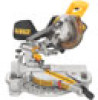
Dewalt DCS361M1 Instruction Manual - Page 10
Changing or Installing a New Saw Blade Fig. 4, Removing the Blade Fig. 3, 4, Installing a Blade Fig - miter saw
 |
View all Dewalt DCS361M1 manuals
Add to My Manuals
Save this manual to your list of manuals |
Page 10 highlights
English FIG. 3 M L K N W O P Q B AR Q A B P W D O N K U C J D J I H C G F E V U TS M C L C Changing or Installing a New Saw Blade (Fig. 4) Refer to Saw Blades under Optional Accessories for correct saw blade. WARNING: To reduce the risk of serious personal injury, turn tool off and remove the battery pack before making any adjustments or removing/installing attachments or accessories. An accidental start-up can cause injury. CAUTION: • Never depress the spindle lock button (AF) while the blade is under power or coasting. • Do not cut metal, masonry or fiber cement product with this miter saw. Removing the Blade (Fig. 3, 4) 1. Remove battery pack (P) from the saw. 2. Raise the arm to the upper position and raise the lower guard (D) as far as possible. 3. Loosen, but do not remove the guard bracket rear screw (Y) by four revolutions. 4. Loosen, but do not remove the guard bracket front screw (X, Fig. 4) until the bracket (Z) can be raised far enough to access the blade screw (AB). Lower guard will remain raised due to the position of the guard bracket screw. 5. Depress the spindle lock button (AF) while carefully rotating the saw blade (AA) by hand until the lock engages. 6. Keeping the button depressed, use the other hand and the 1/4" hex side of the wrench provided (V) to loosen the blade screw (AB). (Turn clockwise, left-hand threads.) 7. Remove the blade screw (AB) using the 1/4" hex side of the wrench provided, the outer clamp washer (AC) and blade (AA). The inner clamp washer (AD) may be left on the spindle (AE). Installing a Blade (Fig. 3, 4) 1. Remove battery pack (P) from the saw. 2. With the arm raised, the lower guard (D) held open and the guard bracket (Z) raised, place the blade (AA) on the spindle (AE) and against the inner blade clamp (AD) with the teeth on the blade pointing in the direction of rotation as marked on the saw. 3. Assemble the outer clamp washer (AC) onto the spindle (AE). 4. Install the blade screw (AB) and, engaging the spindle lock (AF), tighten the screw (AB) firmly with wrench (V) provided (turn counterclockwise, left-hand threads). 5. Return the guard bracket (Z) to its original full down position and firmly tighten both guard bracket screws (X, Y) to hold bracket in place. 8
-
 1
1 -
2
-
3
-
4
-
 5
5 -
 6
6 -
 7
7 -
 8
8 -
 9
9 -
 10
10 -
 11
11 -
 12
12 -
 13
13 -
 14
14 -
 15
15 -
16
-
17
-
18
-
19
-
20
-
21
-
22
-
23
-
24
-
25
-
26
-
27
-
28
-
29
-
30
-
31
-
32
-
33
-
34
-
35
-
36
-
37
-
38
-
39
-
40
-
41
-
42
-
43
-
44
-
45
-
46
-
47
-
48
-
49
-
50
-
51
-
52
-
53
-
54
-
55
-
56
-
57
-
58
-
59
-
60
-
61
-
62
-
63
-
64
 |
 |
