Dewalt DCW600B Instruction Manual - Page 11
Collets, Locking Lever Adjustment Fig. E, Centering the Subbase Fig. A, F1, F2
 |
View all Dewalt DCW600B manuals
Add to My Manuals
Save this manual to your list of manuals |
Page 11 highlights
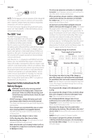
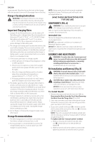
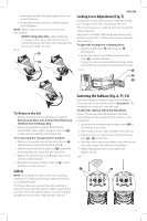
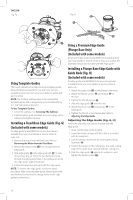
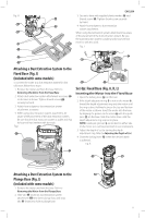
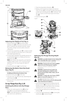
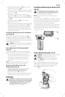
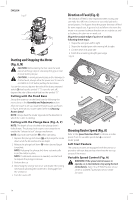
c. Depress the spindle lock button again and turn the wrench clockwise. d. Repeat the procedure until the collet nut reaches desired tightness. NOTE: Tighten collet nut securely to prevent the bit from slipping. NOTICE: Plunge Base Only-When tightening or changing collets, do not allow the wrenches to contact the plunge rods. If the rods are damaged, the plunge action will be restricted. Fig. D 7 22 English Locking Lever Adjustment (Fig. E) Excessive force should not be used to clamp the locking lever. Using excessive force may damage the base. When the locking lever is clamped, the motor should not move in the base. Adjustment is needed if the locking lever will not clamp without excessive force or if the motor moves in the base after clamping. To adjust the locking lever's clamping force: 1. Open the locking lever 12 (fixed base) or 39 (plunge base). 2. Using a hex wrench turn locking lever adjustment screw 23 in small increments. Turning the screw clockwise tightens the lever, while turning the screw counterclockwise loosens the lever. Fig. E 23 12 39 To Remove the Bit 1. Remove the motor unit from the base unit (refer to Removing the Motor from the Fixed Base/Removing the Motor from the Plunge Base). 2. Depress the spindle lock button 7 to hold the spindle shaft in place while turning the collet nut 22 counterclockwise with the wrench provided. To loosen using the "manual ratchet" method: 1. Without removing the wrench from the collet nut 22 , release pressure on the spindle lock button 7 . 2. With the wrench still on the collet nut 22 , reverse the loosening direction to reset the wrench position. 3. Depress the spindle lock button 7 again and turn the wrench counterclockwise. 4. Repeat the procedure until the collet nut 22 is loose and the bit can be removed. Collets NOTE: Never tighten the collet without first installing a router bit in it. Tightening an empty collet, even by hand, can damage the collet. To change collet sizes, unscrew the collet assembly as described above. Install the desired collet by reversing the procedure. The collet and the collet nut are connected. Do not attempt to remove the collet from the collet nut. Centering the Subbase (Fig. A, F1, F2) If you need to adjust, change, or replace the subbase, a centering tool is recommended (refer to Accessories). The centering tool consists of a cone and a pin. To adjust the subbase, follow the steps below. Figure F1 shows adjusting the subbase on the fixed base and Figure F2 shows adjusting the subbase on the plunge base. 1. Loosen but do not remove the subbase screws 24 so the subbase moves freely. 2. Insert the pin into the collet and tighten the collet nut. 3. Insert the motor into the base and clamp the locking lever 12 / 39 on the base. 4. Place the cone on the pin and lightly press down on the cone until it stops. This will center the subbase. 5. While holding down on the cone, tighten the subbase screws. Fig. F1 24 24 9
-
 1
1 -
2
-
3
-
4
-
5
-
 6
6 -
 7
7 -
 8
8 -
 9
9 -
 10
10 -
 11
11 -
 12
12 -
 13
13 -
 14
14 -
 15
15 -
 16
16 -
17
-
18
-
19
-
20
-
21
-
22
-
23
-
24
-
25
-
26
-
27
-
28
-
29
-
30
-
31
-
32
-
33
-
34
-
35
-
36
-
37
-
38
-
39
-
40
-
41
-
42
-
43
-
44
-
45
-
46
-
47
-
48
-
49
-
50
-
51
-
52
-
53
-
54
-
55
-
56
 |
 |
