Dewalt DCW600B Instruction Manual - Page 13
Attaching a Dust Extraction System to the, Fixed Base Fig. I, Included with some models, Plunge Base
 |
View all Dewalt DCW600B manuals
Add to My Manuals
Save this manual to your list of manuals |
Page 13 highlights
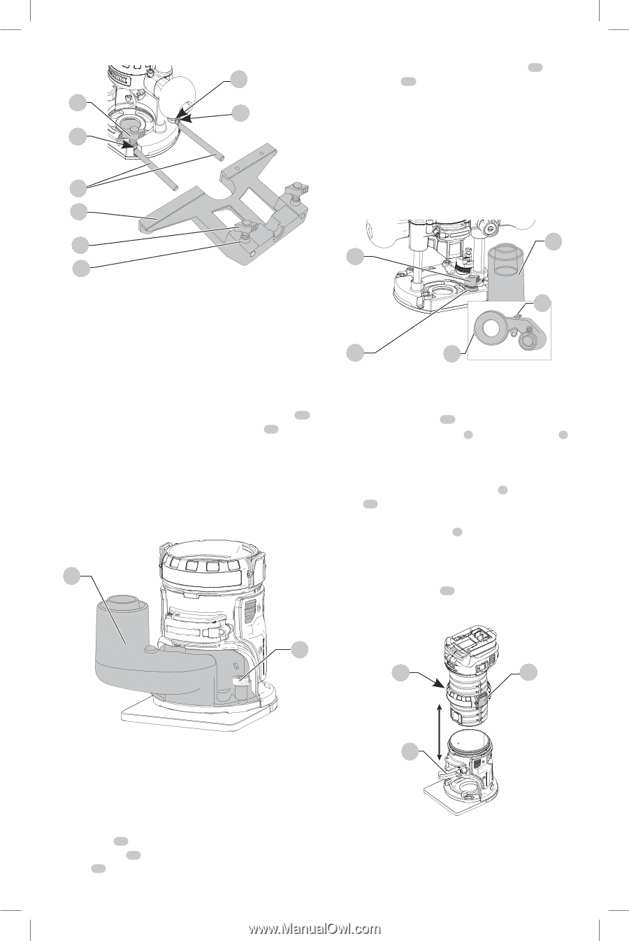
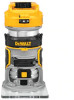
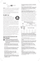
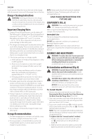
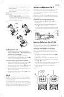
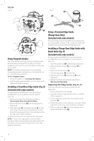
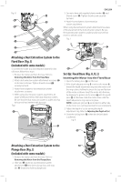
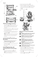
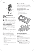
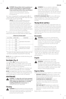
Fig. H 36 37 35 38 English 3. Secure to base with supplied plastic washer 32 and 36 thumb screw 33 . Tighten thumb screw securely by hand. 37 4. Attach hose adapter to dust extraction system attachment. When using dust extraction system attachment, be aware of the placement of the dust extraction system. Be sure the dust extraction system is stable and its hose will not interfere with the work. Fig. J 36 34 33 37 Attaching a Dust Extraction System to the Fixed Base (Fig. I) (Included with some models) To connect the router to a dust extraction system for dust collection, follow these steps: 1. Remove the motor unit from the base. Refer to Removing the Motor from the Fixed Base. 2. Attach dust extraction system attachment accessory 28 to the base as shown. Tighten thumb screws 29 securely by hand. 3. Attach hose adapter to dust extraction system attachment accessory. 4. When using dust extraction system attachment, be aware of the placement of the dust extraction system. Be sure that the dust extraction system is stable and that its hose will not interfere with the work. Fig. I 28 31 32 30 Set-Up: Fixed Base (Fig. A, K, L) Inserting the Motor into the Fixed Base 1. Open the locking lever 12 on the base. 2. If the depth adjustment ring 5 is not on the motor 6 , thread the depth adjustment ring onto the motor until the ring is about halfway between the top and bottom of the motor as shown. Insert the motor into the base by aligning the groove on the motor 6 with the guide pins 17 on the base. Slide the motor down until the depth adjustment ring snaps into place. NOTE: Guide pin grooves 9 are located on either side of the motor so it can be positioned in two orientations. 3. Adjust the depth of cut by turning the depth adjustment ring. Refer to Adjusting the Depth of Cut. 4. Close the locking lever 12 when the desired depth is achieved. Fig. K 29 21 21 Attaching a Dust Extraction System to the 12 Plunge Base (Fig. J) (Included with some models) 1. Remove the motor unit from the base. Refer to Removing the Motor from the Plunge Base. 2. Slide tab 30 (inset) on dust extraction system attachment 34 into slot in plunge base and snap tab 31 (inset) into hole in plunge base. 11
-
 1
1 -
2
-
3
-
4
-
5
-
6
-
7
-
 8
8 -
 9
9 -
 10
10 -
 11
11 -
 12
12 -
 13
13 -
 14
14 -
 15
15 -
 16
16 -
 17
17 -
 18
18 -
19
-
20
-
21
-
22
-
23
-
24
-
25
-
26
-
27
-
28
-
29
-
30
-
31
-
32
-
33
-
34
-
35
-
36
-
37
-
38
-
39
-
40
-
41
-
42
-
43
-
44
-
45
-
46
-
47
-
48
-
49
-
50
-
51
-
52
-
53
-
54
-
55
-
56
 |
 |