Dewalt DCW600B Instruction Manual - Page 12
Installing a Fixed Base Edge Guide Fig. G
 |
View all Dewalt DCW600B manuals
Add to My Manuals
Save this manual to your list of manuals |
Page 12 highlights
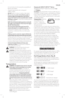
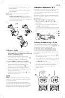
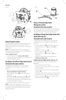
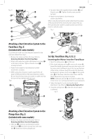
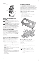
English Fig. F2 Fig. G 26 25 27 24 Using Template Guides The round subbase will accept universal template guides. Recommended accessories for use with your tool are available at extra cost from your local dealer or authorized service center. NOTE: The D-shape subbase does not accommodate template guides and is designed to accommodate bits up to 1-3/8" (34.9 mm) in diameter. To Use Template Guides: 1. Center the subbase. See Centering The Subbase. 2. Install template guide (available as an accessory) on the subbase and tighten securely. Installing a Fixed Base Edge Guide (Fig. G) (Included with some models) An edge guide (model DNP618) for your fixed base is available from your local retailer or service center at extra cost. 1. Remove the motor from the fixed base. Refer to Removing the Motor from the Fixed Base. 2. Remove flat head screws 26 from storage holes on edge guide. 3. Slide edge guide 25 into edge guide slot 27 on side of fixed base (Fig. G). Insert the two flat head screws through the appropriate holes in the subbase to secure the edge guide. Tighten hardware. 4. Follow all instructions included with the edge guide. NOTE: To remove the edge guide, reverse the above procedure. After removing edge guide, always replace the two flat head screws into the storage holes on the edge guide to prevent loss. Using a Premium Edge Guide (Plunge Base Only) (Included with some models) A Premium Edge Guide (model DW6913) is available from your local retailer or service center at extra cost. Follow the assembly instructions included with the edge guide. Installing a Plunge Base Edge Guide with Guide Rods (Fig. H) (Included with some models) An edge guide (model DW6913) for your plunge base is available from your local retailer or service center at extra cost. 1. Attach the guide rods 35 to the plunge router base. 2. Attach the thumb screws 36 and springs 37 to the base. 3. Tighten the thumb screws 36 . 4. Slide the edge guide 38 over the rods. 5. Attach thumb screws 36 and springs 37 to the edge guide. 6. Tighten the thumb screws temporarily. Refer to Adjusting the Edge Guide. Adjusting the Edge Guide (Fig. A, H) Follow the assembly instructions included with the edge guide. 1. Draw a cutting line on the material. 2. Lower the router carriage until the cutter is in contact with the workpiece. 3. Lock the plunge mechanism by releasing the plunge lock lever 16 4. Position the router on the cutting line. The outer cutting edge of the cutter must coincide with the cutting line. 5. Slide the edge guide 38 against the workpiece and tighten the thumb screws 36 . 10
-
 1
1 -
2
-
3
-
4
-
5
-
6
-
 7
7 -
 8
8 -
 9
9 -
 10
10 -
 11
11 -
 12
12 -
 13
13 -
 14
14 -
 15
15 -
 16
16 -
 17
17 -
18
-
19
-
20
-
21
-
22
-
23
-
24
-
25
-
26
-
27
-
28
-
29
-
30
-
31
-
32
-
33
-
34
-
35
-
36
-
37
-
38
-
39
-
40
-
41
-
42
-
43
-
44
-
45
-
46
-
47
-
48
-
49
-
50
-
51
-
52
-
53
-
54
-
55
-
56
 |
 |
