Dewalt DXCMH1393075 Instruction Manual - Page 10
Save These Instructions For Future
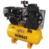 |
View all Dewalt DXCMH1393075 manuals
Add to My Manuals
Save this manual to your list of manuals |
Page 10 highlights
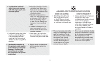
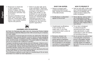
English CAUTION: RISK FROM NOISE WHAT CAN HAPPEN HOW TO PREVENT IT • Under some conditions and duration of use, noise from this product may contribute to hearing loss. • Always wear certified safety equipment: ANSI S12.6 (S3.19) hearing protection. SAVE THESE INSTRUCTIONS FOR FUTURE USE Know Your Air Compressor READ THIS OWNER'S MANUAL AND SAFETY RULES BEFORE OPERATING YOUR UNIT. Compare the illustrations with your unit to familiarize yourself with the location of various controls and adjustments. Save this manual for future reference. FEATURES ELECTRIC START The engine switch (C) can be placed in three positions; START, RUN and OFF. See Starting under Operation for complete starting C instructions. UNLOADER VALVE When the maximum air tank pressure is obtained, the unloader valve (F) will blow-off. This will cause the compressor to exhaust the air to the atmosphere and not the tank. Manual Lock: The manual lock allows you to manually unload the compressor with air F pressure in the air tank. To operate the manual F lock: Rotate the manual lock unloader lever to the open position to prevent air tank pressure OPEN CLOSED buildup. Rotate manual lock unloader lever to the closed position after starting the engine to allow air tank pressure to build. NOTE: Air will not build in tank when manual lock unloader lever in the open position. SAFETY VALVE This valve (G) is designed to prevent system G failures by relieving pressure from the system when the compressed air reaches a predeter 10
-
 1
1 -
2
-
3
-
4
-
 5
5 -
 6
6 -
 7
7 -
 8
8 -
 9
9 -
 10
10 -
 11
11 -
 12
12 -
 13
13 -
 14
14 -
 15
15 -
16
-
17
-
18
-
19
-
20
-
21
-
22
-
23
-
24
-
25
-
26
-
27
-
28
-
29
-
30
-
31
-
32
-
33
-
34
-
35
-
36
-
37
-
38
-
39
-
40
-
41
-
42
-
43
-
44
-
45
-
46
-
47
-
48
-
49
-
50
-
51
-
52
-
53
-
54
-
55
-
56
-
57
-
58
-
59
-
60
-
61
-
62
-
63
-
64
-
65
-
66
-
67
-
68
-
69
-
70
-
71
-
72
-
73
-
74
-
75
-
76
-
77
-
78
-
79
-
80
-
81
-
82
-
83
-
84
-
85
-
86
-
87
-
88
-
89
-
90
-
91
-
92
-
93
-
94
-
95
-
96
-
97
-
98
-
99
-
100
 |
 |
