E-Z-GO RXV - Electric Owner Manual - Page 25
Controls And Indicators
 |
View all E-Z-GO RXV - Electric manuals
Add to My Manuals
Save this manual to your list of manuals |
Page 25 highlights
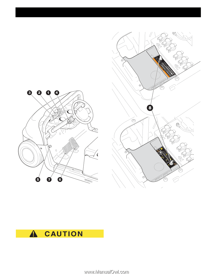
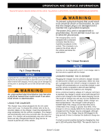
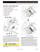
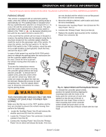
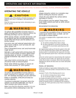
B OPERATION AND SERVICE INFORMATION Read all of manual to become familiar with this vehicle. Pay attention to all NOTICES, CAUTIONS, WARNINGS and DANGERS. CONTROLS AND INDICATORS B Vehicle controls and indicators consist of: 1. Key Switch / Direction Selector 2. Speedometer / State Of Charge Meter (optional) STORAGE 3. Head Light Switch (optional) 4. Turn Signal Switch (optional) 5. Horn Button (optional) 6. Accelerator Pedal 7. Service Brake Pedal 8. Run/Tow Switch l ONN F R OOFF 608769 Fig. 8 Operator Controls & Gauges KEY SWITCH/DIRECTION SELECTOR Located on the dash panel, the key switch/direction selector (1) enables the electrical system of the vehicle to be turned on and off by turning the key; it also functions as the direction selector for forward, neutral or reverse. To prevent inadvertent operation of the vehicle when left unattended, the key should be turned to the 'OFF' position and removed. To reduce the possibility of component damage, the vehicle must be stopped before moving the key switch/ direction selector. Fig. 9 Run/Tow Switch SPEEDOMETER / STATE OF CHARGE (SOC) METER (OPTIONAL EQUIPMENT) If the vehicle is equipped with a speedometer / state of charge meter (2), it is located in the dash panel to the left of the key switch (1) (Ref. Fig. 8). The speedometer displays the MPH, SOC, vehicle mileage, and errors/ warnings. The SOC meter indicates the amount of usable power in the batteries. The state of charge meter on the electric vehicle shows the condition of the battery pack with F indicating a full charge on the battery pack and E indicating the battery pack needs to be charged. Owner's Guide Page 5
-
 1
1 -
2
-
3
-
4
-
5
-
6
-
7
-
8
-
9
-
10
-
11
-
12
-
13
-
14
-
15
-
16
-
17
-
18
-
19
-
 20
20 -
 21
21 -
 22
22 -
 23
23 -
 24
24 -
 25
25 -
 26
26 -
 27
27 -
 28
28 -
 29
29 -
 30
30 -
31
-
32
-
33
-
34
-
35
-
36
-
37
-
38
-
39
-
40
-
41
-
42
-
43
-
44
-
45
-
46
-
47
-
48
-
49
-
50
-
51
-
52
-
53
-
54
-
55
-
56
-
57
-
58
-
59
-
60
 |
 |