E-Z-GO RXV - Electric Owner Manual - Page 26
Headlight Switch Optional Equip, Turn Signal Switch Optional Equip, Horn Optional Equipment, - motors
 |
View all E-Z-GO RXV - Electric manuals
Add to My Manuals
Save this manual to your list of manuals |
Page 26 highlights
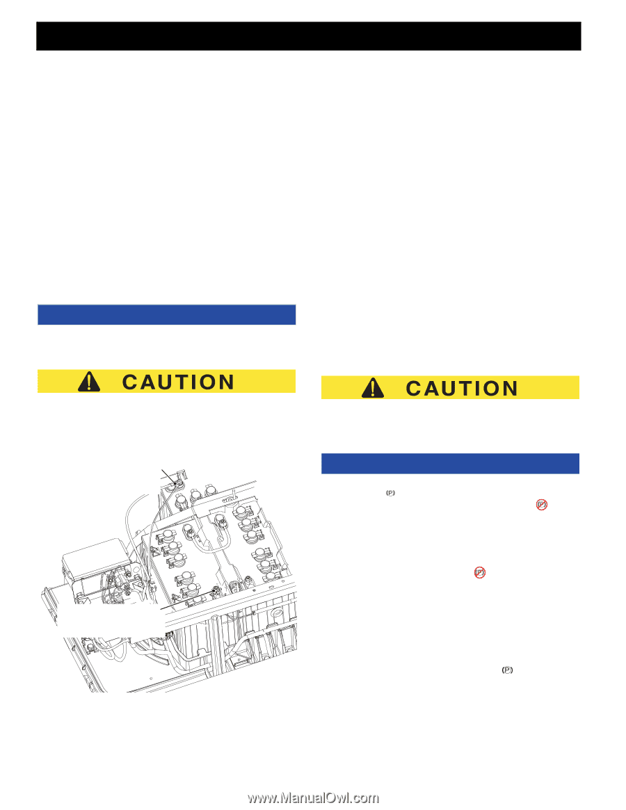
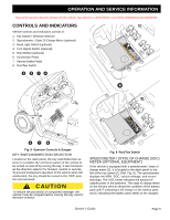
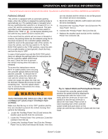
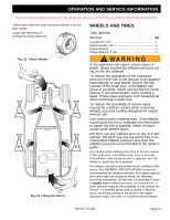
OPERATION AND SERVICE INFORMATION Read all of manual to become familiar with this vehicle. Pay attention to all NOTICES, CAUTIONS, WARNINGS and DANGERS. BHEADLIGHT SWITCH (OPTIONAL EQUIPMENT) If the vehicle is equipped with headlights, the ON/OFF switch (3) is located on the instrument panel to the left of the key switch (1) (Ref. Fig. 8). TURN SIGNAL SWITCH (OPTIONAL EQUIPMENT) If the vehicle is equipped with turn signals, the switch (4) is mounted on the steering column (Ref. Fig. 8). HORN (OPTIONAL EQUIPMENT) If the vehicle is equipped with a horn, the horn button (5) is located on the driver's side floorboard; depressing the button will sound the vehicle's horn (Ref. Fig. 8). NOTICE If the vehicle is equipped with factory installed custom accessories, some accessories remain operational with the key switch in the 'OFF' position. harness must be connected across the entire 48 volt battery pack. This can be done by connecting to the two battery terminals shown in the illustration.(Ref. Fig. 10) If the accessory requires voltage other than 48 volts a DC to DC converter must be used to change the voltage to the amount required by the accessory. A DC to DC converter is available through E-Z-GO Service Parts. The Operational Performance Guarantee of 2 rounds per day shall be void if non-factory accessories that use more than 1 Amp/Hour of energy per round are installed on the vehicle. ACCELERATOR & BRAKE PEDALS With the key switch in the 'F' or 'R' position, depressing the accelerator pedal (6) starts the motor and will move the vehicle in the direction indicated on the key switch/ direction selector. This vehicle is equipped with a motor brake; when the accelerator pedal is released, the motor will stop. To stop the vehicle more quickly , depress the service brake pedal (7)(Ref. Fig. 8). RUN/TOW SWITCH ALL accessories that do NOT use the accessory wiring harness MUST be connected to draw from the entire 48 Volt battery pack. A DC to DC converter is required for accessories that require voltage other than 48 volts to operate properly. ATTACH NEGATIVE WIRE FROM ACCESSORY TO (-) BATTERY TERMINAL ATTACH POWER WIRE FROM ACCESSORY TO (+) BATTERY TERMINAL Fig. 10 Attach Accessory Wires to Battery Pack Accessories, including a DC to DC converter, that are connected to this vehicle and do not use the accessory Before attempting to tow the vehicle, turn the key switch to 'N' and move the Run/Tow switch to the 'TOW' position. Failure to do so will damage the controller or motor. NOTICE The RUN/TOW switch should always be returned to the 'RUN/ /STORAGE' or (on European Models) position after tow- ing the vehicle. If the switch is left in the 'TOW' or (on European Models) position for an extended period of time it will drain the batteries. The run/tow switch (8) is located under the seat on the passenger side of the vehicle (Ref. Fig. 9). With the switch in the 'TOW' or (on European Models) position and the key in 'N': • the electronic parking brake is deactivated, which allows the vehicle to be towed or roll freely, except in the event of a controller failure • the service brake is still active • the reverse warning beeper is deactivated With the switch in 'RUN/STORAGE' or (on Europe- an Models) position: • the electronic parking brake is deactivated and the reverse warning beeper features are activated Page 6 Owner's Guide
-
 1
1 -
2
-
3
-
4
-
5
-
6
-
7
-
8
-
9
-
10
-
11
-
12
-
13
-
14
-
15
-
16
-
17
-
18
-
19
-
20
-
 21
21 -
 22
22 -
 23
23 -
 24
24 -
 25
25 -
 26
26 -
 27
27 -
 28
28 -
 29
29 -
 30
30 -
 31
31 -
32
-
33
-
34
-
35
-
36
-
37
-
38
-
39
-
40
-
41
-
42
-
43
-
44
-
45
-
46
-
47
-
48
-
49
-
50
-
51
-
52
-
53
-
54
-
55
-
56
-
57
-
58
-
59
-
60
 |
 |