E-Z-GO RXV - Electric Owner Manual - Page 27
This Procedure Should Only Be Per, Formed By Qualified Trained Per, Sonnel.
 |
View all E-Z-GO RXV - Electric manuals
Add to My Manuals
Save this manual to your list of manuals |
Page 27 highlights
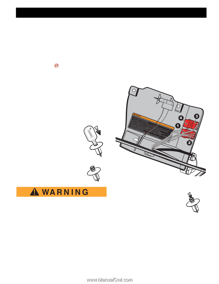
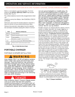
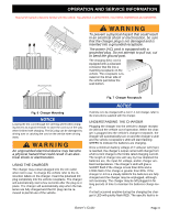
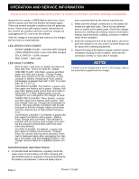
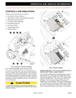
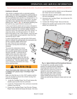
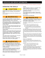
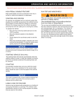
B OPERATION AND SERVICE INFORMATION Read all of manual to become familiar with this vehicle. Pay attention to all NOTICES, CAUTIONS, WARNINGS and DANGERS. PARKING BRAKE This vehicle is equipped with an automatic parking brake; when the vehicle is stopped the parking brake is automatically set. The parking brake is released when the key switch/direction selector is in forward ('F') or re- verse ('R') and the accelerator is depressed. The park- ing brake is also released when the run/tow switch is placed in the 'TOW' or (on European Models) posi- tion with the key switch turned to neutral ('N'). In the event that the vehicle will not move in forward or reverse, the parking brake can be released using the instructions located on the controller splash shield beneath the seat on the passenger side of the vehicle. To move the vehicle, turn the key switch to 'N', flip the RUN-TOW switch to the 'TOW' position, move the vehicle to a safe location on level ground, chock the tires, and turn the key to 'OFF'. In case of total power loss and the RUN-TOW switch does not release the parking brake the instructions below the controller splash shield must be used. Chock the tires to prevent the vehicle moving when the brake is released. To access the instructions remove three re-usable plastic rivets securing the controller splash shield to the body and the controller. To remove the reusable rivets, press the center of the rivet with the vehicle key. When the center pin snaps into place the rivet can be removed. Repeat the process for each remaining rivet. Turn the splash shield over to reveal the instructions for releasing the parking brake. THIS PROCEDURE SHOULD ONLY BE PERFORMED BY QUALIFIED TRAINED PERSONNEL. Make sure that the key is in the 'OFF' position and the tires are chocked to prevent the vehicle moving; then perform the following: 1. Locate the 'Auxiliary Power' line (3) and remove the weather pack seal (4) from the connector. 2. Locate the 'Primary Power' line connector (1) and disconnect it from line (2). 3. Connect the 'Auxiliary Power' line (3) to the 'Primary Power' line (1) which will release the brake. If the tires B are not chocked and the vehicle is not on flat ground the vehicle will move immediately. 4. Move the vehicle to desired, safe location and chock the tires immediately. 5. Disconnect the 'Auxiliary Power' line (3) from the 'Pri- mary Power' line (1). 6. Connect the 'Primary Power' line (1) to line (2). 7. Replace the weather pack seal (4) on the 'Auxiliary Power' line connector (3). pRrAoDeNMccICeSDoCoAIdnCvdoITuUIdneTenOnrOeeOSunnevNCTncrteNEseAHinattNfcLhiVysfIftTtYSoEtyhieOhctH'leChBAPllOteoIehEeDRYTuWfweitgOxTV'Qo'iBPeiAnon'ClEAUiaArtdigUaEtaiAHutiemTrDhloXaxLysITPenUaCliIIillFELoPrrirRLakeSIywIRoPEEAeErdaewyPDYayRSfrlTecoeoPTHYtLDOktworcRoyOoF'RaPSewAstlUaMgithArsOneIieiLuN'oeOlIeaArDWliuNnEid'l'Vnn(OrD.lOeE(a3dieEe4nlFNn)RPiT)en(tFIdLEt1'hMoetoY'(ARo)eps3pMf'SBNca'Pt)ooaRhOoEErDraslskuenNilDTnimnotnRoNiAOidIt-oweauAtEEuponcCrrtTLxCyelwrttiLoEiaonhml'OEPipnreLaSeAooNeYddarwsvRwyrNnei'lieItcynedFPVEchirthEonoyChdN'oHnowseDilcTOsiIutnkeOlCcWrerT'e'roPELuvtrelnESi(OReceir1nanetlpFINN)etieMsgaRhoOwcriL(eAOtnrTot3ohErRMumst)iRhVPcpnYaceAaehrEadnalenNePc,LlwdnvuiakOncUesiaGplhreNSnelWleeR.ortSe(TrsecE2OiAfahunklo)RelFeU.alrta(Et'mdBiN4rs(ivAer)1nDearesR,fek.rrt,DE2qehotIeA)uEemMTniFAoArbMtetOTNMrhmdEaHDReookDsvBecvoSeIeoeA.ErrATnvmTTSPFhinHEceEEeEeeLInRRTScVYtFIte.YoOOWhriRU.cILMlSeLE:IDNJURY 609694 Fig. 11 Splash Shield and Parking Brake Release To reinstall the controller splash shield, position the splash shield by aligning the mounting holes with the holes in the body, push the center pin of each rivet upward so that the top of the pin is above the rivet head. Place a rivet in each mounting hole of the controller splash shield and push down on the center pin until the top of the pin is flush with the rivet head. Owner's Guide Page 7
-
 1
1 -
2
-
3
-
4
-
5
-
6
-
7
-
8
-
9
-
10
-
11
-
12
-
13
-
14
-
15
-
16
-
17
-
18
-
19
-
20
-
21
-
 22
22 -
 23
23 -
 24
24 -
 25
25 -
 26
26 -
 27
27 -
 28
28 -
 29
29 -
 30
30 -
 31
31 -
 32
32 -
33
-
34
-
35
-
36
-
37
-
38
-
39
-
40
-
41
-
42
-
43
-
44
-
45
-
46
-
47
-
48
-
49
-
50
-
51
-
52
-
53
-
54
-
55
-
56
-
57
-
58
-
59
-
60
 |
 |