Epson ActionNote 660C User Manual - Page 80
in step 8 and secure it to the back of the computer with its
 |
View all Epson ActionNote 660C manuals
Add to My Manuals
Save this manual to your list of manuals |
Page 80 highlights
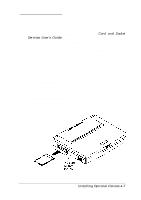
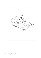
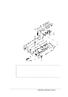
9. Locate the two connectors on the base of the memory module so you can align them with the two small sockets on the system board. 10. Align the module connectors with the computer's sockets, as shown below, and lower the module into position. 11 Carefully press the module connectors into the sockets, making sure you align the connector pins and the socket holes. Do not force the connectors into the sockets; if you have trouble, remove the module and try again. 12 Now replace the CPU heat spreader in the position shown in step 8 and secure it to the back of the computer with its retaining screw. Close the port cover door. 13 Replace the memory module cover in the position shown in step 5 and secure it to the bottom of the computer with its two retaining screws. 4-12 Installing Optional Devices
-
 1
1 -
2
-
3
-
4
-
5
-
6
-
7
-
8
-
9
-
10
-
11
-
12
-
13
-
14
-
15
-
16
-
17
-
18
-
19
-
20
-
21
-
22
-
23
-
24
-
25
-
26
-
27
-
28
-
29
-
30
-
31
-
32
-
33
-
34
-
35
-
36
-
37
-
38
-
39
-
40
-
41
-
42
-
43
-
44
-
45
-
46
-
47
-
48
-
49
-
50
-
51
-
52
-
53
-
54
-
55
-
56
-
57
-
58
-
59
-
60
-
61
-
62
-
63
-
64
-
65
-
66
-
67
-
68
-
69
-
70
-
71
-
72
-
73
-
74
-
 75
75 -
 76
76 -
 77
77 -
 78
78 -
 79
79 -
 80
80 -
 81
81 -
 82
82 -
 83
83 -
 84
84 -
 85
85 -
86
-
87
-
88
-
89
-
90
-
91
-
92
-
93
-
94
-
95
-
96
-
97
-
98
-
99
-
100
-
101
-
102
-
103
-
104
-
105
-
106
-
107
-
108
-
109
-
110
-
111
-
112
-
113
-
114
 |
 |
