Epson Ensemble HD 8100 Installation Guide - Page 8
antenna system
 |
View all Epson Ensemble HD 8100 manuals
Add to My Manuals
Save this manual to your list of manuals |
Page 8 highlights
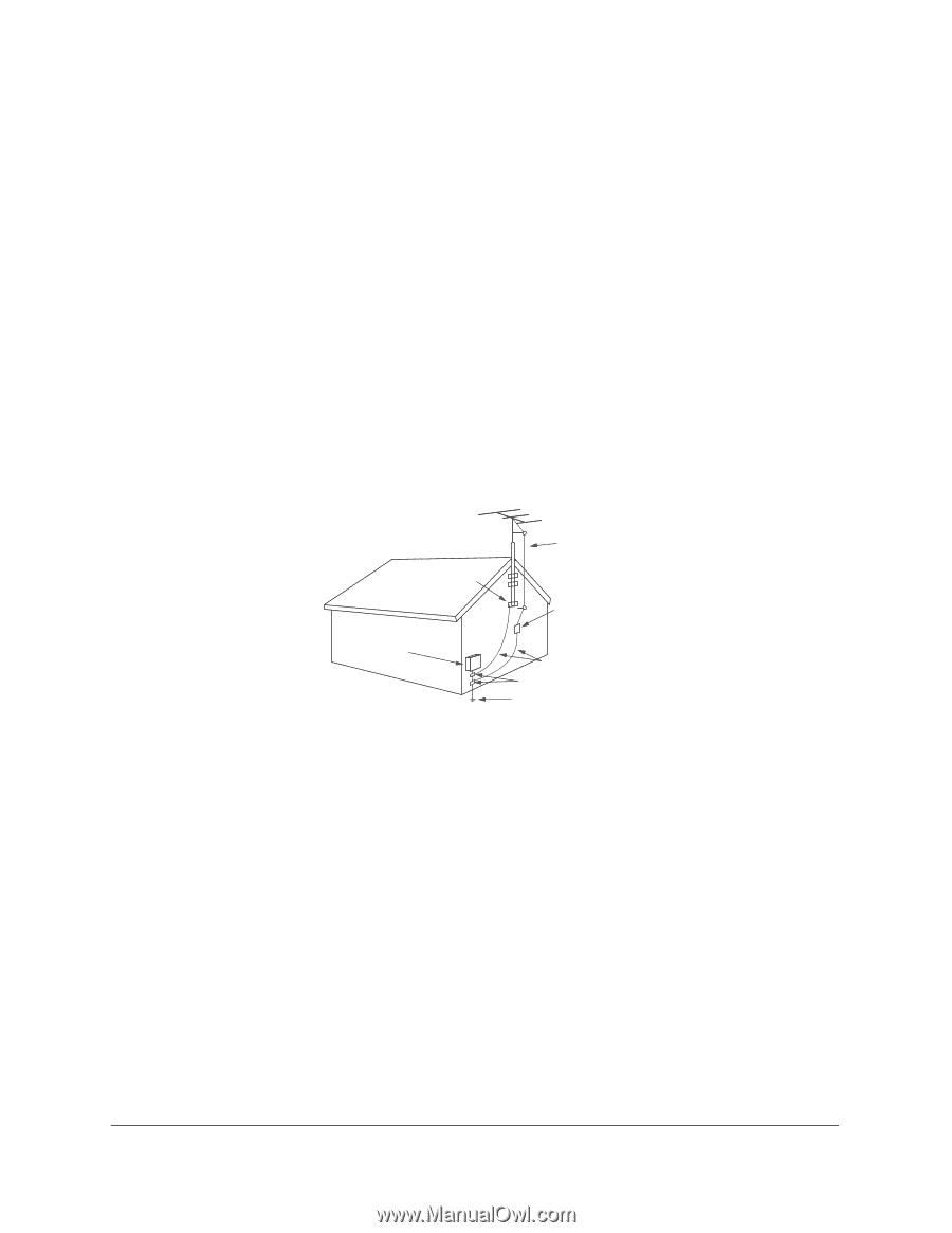
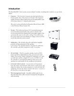
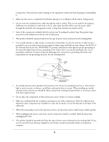
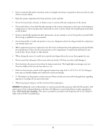
routing wires. Personal injury and/or damage to the equipment could result from dropping or mishandling it. • Make sure the screen is completely closed before placing it on or lifting it off the wall or ceiling mount. • Do not route the included power cables through the wall or ceiling. They are not rated for this purpose. Deliberate mis-installation could result in fire or other safety hazards. Either route the power cables through the included wire management tracks, or plug them directly into nearby outlets. • Some of the components included with this system may be packaged in plastic bags. Keep plastic bags away from small children to avoid any risk of suffocation. • This product should be operated only from the type of power source indicated on the marking label. • If an outside antenna or cable system is connected to the product, be sure the antenna or cable system is grounded so as to provide some protection against voltage surges and built-up static charges. Article 810 of the National Electrical Code, ANSI/NFPA 70, provides information with regard to proper grounding of the mast and supporting structure, grounding of the lead-in wire to an antenna discharge unit, size of grounding conductors, location of antenna-discharge unit, connection to grounding electrodes, and requirements for the grounding electrode. See the drawing below. ELECTRIC SERVICE EQUIPMENT GROUND CLAMP ANTENNA LEAD IN WIRE ANTENNA DISCHARGE UNIT (NEC SECTION 810-20) GROUNDING CONDUCTORS (NEC SECTION 810-21) GROUND CLAMPS POWER SERVICE GROUNDING ELECTRODE SYSTEM (NEC ART 250, PART H) • An outside antenna system should not be located in the vicinity of overhead power lines or other electric light or power circuits, or where it can fall into such power lines or circuits. When installing an outside antenna system, extreme care should be taken to keep from touching such power lines or circuits as contact with them might be fatal. • Do not place the components of this system near sources of heat or in direct sunlight. • Make sure nothing blocks the ventilation openings on any of the components. Allow for sufficient heat dispersion when components are installed on a rack. Do not block or cover the heatsink on the back of the subwoofer. • Where the mains plug is used as the disconnect device, the disconnect device shall remain readily operable. • When unplugging the power cord of any system component, handle it carefully. Hold the plug when unplugging the cord. • This product should be operated only from the type of power source indicated on the marking label. If you are not sure of the type of power supplied in your home, consult your product dealer or local power company. 8
-
 1
1 -
2
-
 3
3 -
 4
4 -
 5
5 -
 6
6 -
 7
7 -
 8
8 -
 9
9 -
 10
10 -
 11
11 -
 12
12 -
 13
13 -
14
-
15
-
16
-
17
-
18
-
19
-
20
-
21
-
22
-
23
-
24
-
25
-
26
-
27
-
28
-
29
-
30
-
31
-
32
-
33
-
34
-
35
-
36
-
37
-
38
-
39
-
40
-
41
-
42
-
43
-
44
-
45
-
46
-
47
-
48
-
49
-
50
-
51
-
52
-
53
-
54
-
55
-
56
-
57
-
58
-
59
-
60
-
61
-
62
-
63
-
64
-
65
-
66
-
67
-
68
-
69
-
70
-
71
 |
 |