Epson LQ-1010 User Manual - Page 237
Technical Specifications 8-9, Logic ground level.
 |
View all Epson LQ-1010 manuals
Add to My Manuals
Save this manual to your list of manuals |
Page 237 highlights
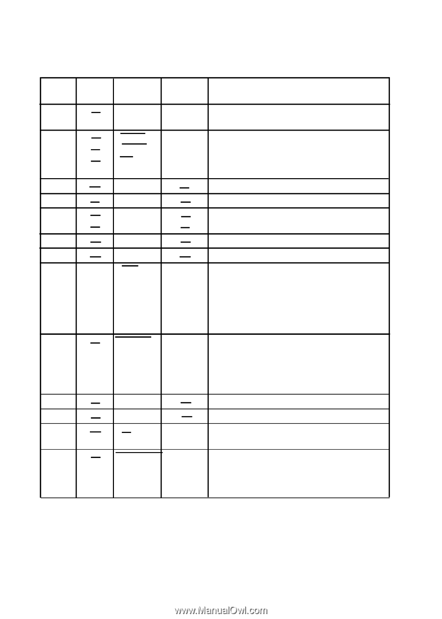
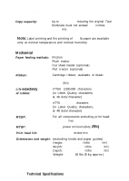
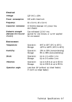
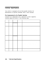
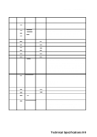
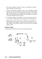
Interface Specifications Signal Pin 13 14 15 16 17 18 19-30 31 32 33 34 35 36 Return Pin 16 Signal Direction SLCT OUT AUTO IN FEED XT NC GND CHASSIS GND NC GND INIT IN ERROR OUT GND NC OUT SLCT IN IN Description Pulled up to + 5 volts through 3.3 Kohm resistance. When this signal is LOW, the paper is automatically fed 1 line after printing. (The Signal level can be fixed to this by setting DIP switch 2-4 to on.) Not used. Logic ground level. Printer's chassis ground, which is isolated from the logic ground. Not used. Twisted-pair return signal ground level. When this level becomes LOW, the printer controller is reset to its power-up state and the print buffer is cleared. This level is normally HIGH; its pulse width must be more than 50 microseconds at the receiving terminal. This level becomes LOW when the printer is: 1) in paper out state. 2) off line. 3) in error state. Same as for Pins 19-30 Not used Pulled up to 5V through 3.3 Kohm resistance. The DC1/DC3 code is valid only when this signal is HIGH. (Internal fixing can be carried out with Jumper J10. The level of this signal is factory-set to LOW.) Technical Specifications 8-9
-
 1
1 -
2
-
3
-
4
-
5
-
6
-
7
-
8
-
9
-
10
-
11
-
12
-
13
-
14
-
15
-
16
-
17
-
18
-
19
-
20
-
21
-
22
-
23
-
24
-
25
-
26
-
27
-
28
-
29
-
30
-
31
-
32
-
33
-
34
-
35
-
36
-
37
-
38
-
39
-
40
-
41
-
42
-
43
-
44
-
45
-
46
-
47
-
48
-
49
-
50
-
51
-
52
-
53
-
54
-
55
-
56
-
57
-
58
-
59
-
60
-
61
-
62
-
63
-
64
-
65
-
66
-
67
-
68
-
69
-
70
-
71
-
72
-
73
-
74
-
75
-
76
-
77
-
78
-
79
-
80
-
81
-
82
-
83
-
84
-
85
-
86
-
87
-
88
-
89
-
90
-
91
-
92
-
93
-
94
-
95
-
96
-
97
-
98
-
99
-
100
-
101
-
102
-
103
-
104
-
105
-
106
-
107
-
108
-
109
-
110
-
111
-
112
-
113
-
114
-
115
-
116
-
117
-
118
-
119
-
120
-
121
-
122
-
123
-
124
-
125
-
126
-
127
-
128
-
129
-
130
-
131
-
132
-
133
-
134
-
135
-
136
-
137
-
138
-
139
-
140
-
141
-
142
-
143
-
144
-
145
-
146
-
147
-
148
-
149
-
150
-
151
-
152
-
153
-
154
-
155
-
156
-
157
-
158
-
159
-
160
-
161
-
162
-
163
-
164
-
165
-
166
-
167
-
168
-
169
-
170
-
171
-
172
-
173
-
174
-
175
-
176
-
177
-
178
-
179
-
180
-
181
-
182
-
183
-
184
-
185
-
186
-
187
-
188
-
189
-
190
-
191
-
192
-
193
-
194
-
195
-
196
-
197
-
198
-
199
-
200
-
201
-
202
-
203
-
204
-
205
-
206
-
207
-
208
-
209
-
210
-
211
-
212
-
213
-
214
-
215
-
216
-
217
-
218
-
219
-
220
-
221
-
222
-
223
-
224
-
225
-
226
-
227
-
228
-
229
-
230
-
231
-
 232
232 -
 233
233 -
 234
234 -
 235
235 -
 236
236 -
 237
237 -
 238
238 -
 239
239 -
 240
240 -
 241
241 -
 242
242 -
243
-
244
-
245
-
246
-
247
-
248
-
249
-
250
-
251
-
252
-
253
-
254
-
255
-
256
-
257
-
258
-
259
-
260
-
261
-
262
-
263
-
264
-
265
-
266
-
267
-
268
-
269
-
270
-
271
-
272
-
273
-
274
-
275
-
276
-
277
-
278
-
279
-
280
-
281
-
282
-
283
-
284
-
285
-
286
-
287
-
288
-
289
-
290
-
291
-
292
-
293
-
294
-
295
-
296
-
297
-
298
-
299
-
300
-
301
-
302
-
303
-
304
-
305
-
306
-
307
-
308
 |
 |