Fluke 345 FE 345 Users Manual - Page 67
Detailed View of Harmonic Recording Display, on the display.
 |
View all Fluke 345 manuals
Add to My Manuals
Save this manual to your list of manuals |
Page 67 highlights
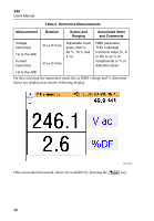
Power Quality Clamp Meter Measurement Function Overview eln37.bmp The upper part of the orange bar is the maximum value of the harmonic, and the lowest part of the orange bar is the minimum value measured during the logging period. The elapsed time of the logging period is displayed as Run Time on the display. The cursor may be moved left or right to select individual harmonics from dc to the 40th harmonic. Figure 16 shows the detailed view of the harmonic recording display. Figure 16. Detailed View of Harmonic Recording Display eln38.bmp 53
-
 1
1 -
2
-
3
-
4
-
5
-
6
-
7
-
8
-
9
-
10
-
11
-
12
-
13
-
14
-
15
-
16
-
17
-
18
-
19
-
20
-
21
-
22
-
23
-
24
-
25
-
26
-
27
-
28
-
29
-
30
-
31
-
32
-
33
-
34
-
35
-
36
-
37
-
38
-
39
-
40
-
41
-
42
-
43
-
44
-
45
-
46
-
47
-
48
-
49
-
50
-
51
-
52
-
53
-
54
-
55
-
56
-
57
-
58
-
59
-
60
-
61
-
 62
62 -
 63
63 -
 64
64 -
 65
65 -
 66
66 -
 67
67 -
 68
68 -
 69
69 -
 70
70 -
 71
71 -
 72
72 -
73
-
74
-
75
-
76
-
77
-
78
-
79
-
80
 |
 |

Power Quality Clamp Meter
Measurement Function Overview
53
eln37.bmp
The upper part of the orange bar is the maximum value of the harmonic, and
the lowest part of the orange bar is the minimum value measured during the
logging period. The elapsed time of the logging period is displayed as
Run
Time
on the display.
The cursor may be moved left or right to select individual harmonics from dc
to the 40
th
harmonic.
Figure 16 shows the detailed view of the harmonic recording display.
eln38.bmp
Figure 16. Detailed View of Harmonic Recording Display