GE AJCQ10ACC Owners Manual - Page 9
Fan Switch, Temperature Limitiug
 |
View all GE AJCQ10ACC manuals
Add to My Manuals
Save this manual to your list of manuals |
Page 9 highlights
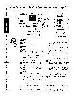
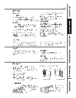
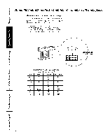
Fan Switch "['o reach the tim switch(es) l(mov( the hont grille. OnHeagCooland HeatPumpmodels,tile tim switch level_ are locaL((1 in holes acc(ss(d through the control box. The top switch is fbr COOLsetting_ and the bottom switch is tot HEATsetting_. I sea small screwdriver to change the setting. The unit is shipped i_-om tile fhcto_T set in tile CONrsetting fbr COOLand in the CYCLEseuing for HEAT Cooloolymodelshave a zockez switch on the hont ot the control box. When set at CYCLE(down) the the cycles on and offwhen cooling. When set at CONY(confimlous, up) the the luns all the time, providing a more b_dm_ced lempec, mne. The unit is shipl)ed in lhe CONTs( tting. ge.com Temperature Limitiug Limiting the maximum and minimum setting _, l)r(.vcnts usel-_ fl-om tulning the control 1o the exlreme heat or cool positions. "File normal range of the lump control is approximately (?')°Fto 85°E Tim control range ma} b( narrowed by tile use of'the tempemun-( limiting screws locat_ d behind the contrtd l)anel. Limits(_ heat temg Limits cool temp Each position equals approximately 3°E Veut Control The vent control is located behind tim front grille on file right skte ot the air discharge area. When set at CLOSEo, nly the air inside the room will be circulamd and conditioned. When set at OPEN,some inside air is exhausted outsid(. rI() open or close the v('nt: l. R(move ll_e front grille. 2. Remove the vent card screw. 3. Remove vent card, turn it over and rel)lnce il by locating rear hole in card over locating pin inside air discharge and rcauaching screw at fi-ont. The unit leavesthefactoH setat the CLOSEposition. Locatinghole Locatinghole OPENposition (Meshendtowardback) CLOSEposition {Meshendtowald flont} A# Direction IIorizontal louvers on the front grilk l(t VO!/ (;Olltl'ol the air (lirection up alld dowll. P,em(y,e tile front grille u_ ar!just tile vcrtical louvcrs side-t(_-side 1o direct the air left or right. ,9
-
 1
1 -
2
-
3
-
 4
4 -
 5
5 -
 6
6 -
 7
7 -
 8
8 -
 9
9 -
 10
10 -
 11
11 -
 12
12 -
 13
13 -
 14
14 -
15
-
16
-
17
-
18
-
19
-
20
-
21
-
22
-
23
-
24
-
25
-
26
-
27
-
28
-
29
-
30
-
31
-
32
-
33
-
34
-
35
-
36
-
37
-
38
-
39
-
40
-
41
-
42
-
43
-
44
-
45
-
46
-
47
-
48
-
49
-
50
-
51
-
52
-
53
-
54
-
55
-
56
-
57
-
58
-
59
-
60
-
61
-
62
-
63
-
64
-
65
-
66
-
67
-
68
-
69
-
70
-
71
-
72
-
73
-
74
-
75
-
76
 |
 |
