Gigabyte GA-N680SLI-DQ6 Manual - Page 85
B. GIGABYTE SATA2 Controller, Installing SATA hard drives in your computer, Configuring SATA
 |
View all Gigabyte GA-N680SLI-DQ6 manuals
Add to My Manuals
Save this manual to your list of manuals |
Page 85 highlights
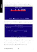
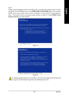
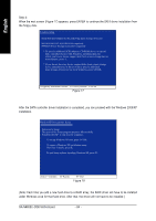
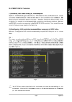
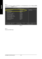
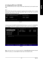
English B. GIGABYTE SATA2 Controller (1) Installing SATA hard drive(s) in your computer Attach one end of the SATA signal cable to the rear of the SATA hard drive and the other end to available SATA port(s) on the motherboard. If there are more than one SATA controller on your motherboard, refer to the connectors introduction section of the user's manual to identify the SATA controller for the connectors. (For example, on the GA-N680SLI-DQ6 motherboard, the GSATAII0, GSATAII1, GSATAII2 and GSATAII3 connectors are supported by the GIGABYTE SATA2 controller.) Then connect the power connector from your power supply to the hard drive. (2) Configuring SATA controller mode and boot sequence in BIOS Setup Make sure to configure the SATA controller mode correctly in system BIOS Setup and set the first boot devce. Step 1: Turn on your computer and press Del to enter BIOS Setup during POST (Power-On Self Test). In BIOS Setup, go to Integrated Periperals, ensure that the Onboard SATA-II Ctrl1 or Onboard SATA-II Ctrl2 is enabled. Then set Onboard SATA-II Ctrl1 Mode or Onboard SATA-II Ctrl2 Mode to RAID before configuring RAID. If you do not want to create RAID, set this item to IDE or AHCI, depending on your need (Figure 1). CMOS Setup Utility-Copyright (C) 1984-2007 Award Software Integrated Peripherals On-Chip IDE Channel0 IDE Prefetch Mode NV Serial-ATA Controller Serial-ATA RAID Config Onboard SATA-II Ctrl1 Onboard SATA-II Ctrl1 Mode Onboard SATA-II Ctrl2 Onboard SATA-II Ctrl2 Mode On-Chip MAC Lan On-Chip MAC1 Lan On-Chip SMART LAN Onboard LAN1 Controller Onboard LAN2 Controller Onboard LAN Boot ROM Onboard Audio Function On-Chip USB USB Keyboard Support USB Mouse Support Onboard 1394 [Enabled] [Enabled] [All Enabled] [Press Enter] [Enabled] [RAID] [Enabled] [RAID] [Auto] [Auto] [Press Enter] [Enabled] [Enabled] [Disabled] [Auto] [V1.1+V2.0] [Disabled] [Disabled] [Enabled] Item Help Menu Level : Move Enter: Select F5: Previous Values +/-/PU/PD: Value F10: Save F6: Fail-Safe Defaults ESC: Exit F1: General Help F7: Optimized Defaults Figure 1 The BIOS Setup menus described in this section may not show the exact settings for your motherboard. The actual BIOS Setup menu options you will see shall depend on the motherboard you have and the BIOS version. - 85 - Appendix
-
 1
1 -
2
-
3
-
4
-
5
-
6
-
7
-
8
-
9
-
10
-
11
-
12
-
13
-
14
-
15
-
16
-
17
-
18
-
19
-
20
-
21
-
22
-
23
-
24
-
25
-
26
-
27
-
28
-
29
-
30
-
31
-
32
-
33
-
34
-
35
-
36
-
37
-
38
-
39
-
40
-
41
-
42
-
43
-
44
-
45
-
46
-
47
-
48
-
49
-
50
-
51
-
52
-
53
-
54
-
55
-
56
-
57
-
58
-
59
-
60
-
61
-
62
-
63
-
64
-
65
-
66
-
67
-
68
-
69
-
70
-
71
-
72
-
73
-
74
-
75
-
76
-
77
-
78
-
79
-
 80
80 -
 81
81 -
 82
82 -
 83
83 -
 84
84 -
 85
85 -
 86
86 -
 87
87 -
 88
88 -
 89
89 -
 90
90 -
91
-
92
-
93
-
94
-
95
-
96
-
97
-
98
-
99
-
100
-
101
-
102
-
103
-
104
-
105
-
106
-
107
-
108
-
109
-
110
-
111
-
112
 |
 |
