Gigabyte MNNM1PI Manual
Gigabyte MNNM1PI Manual
 |
View all Gigabyte MNNM1PI manuals
Add to My Manuals
Save this manual to your list of manuals |
Gigabyte MNNM1PI manual content summary:
- Gigabyte MNNM1PI | Manual - Page 1
MNNM1PI Intel® mini-ITX Motherboard USER'S MANUAL Intel® mini-ITX Motherboard Rev. 1001 * The WEEE marking on the product indicates this product must not be disposed of with user's other household waste and must be handed - Gigabyte MNNM1PI | Manual - Page 2
For detailed product information and specifications, please carefully read the "Product User Manual". For detailed information related to Gigabyte's unique features, please go to "Technology Guide" section on Gigabyte's website to read or download the information you need. For more product details - Gigabyte MNNM1PI | Manual - Page 3
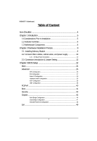
MNNM1PI Motherboard Table of Content Item Checklist 4 Chapter 1 Introduction 5 1-1Considerations Prior to Installation 5 1.2 Features Summary 6 1.3 Motherboard Components 8 Chapter 2 Hardware Installation Process 9 2-1: Installing Memory Module 9 2-2: Connect ribbon cables, cabinet wires, and - Gigabyte MNNM1PI | Manual - Page 4
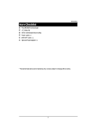
Item Checklist The MNNM1PI motherboard I/O Shield Kit CD for motherboard driver & utility Power cable x 1 B4P/S4P Cable x 1 Optional Power Adapter x 1 Introduction * The items listed above are for reference only, and are subject to change without notice. 4 - Gigabyte MNNM1PI | Manual - Page 5
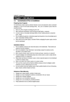
MNNM1PI Motherboard Chapter 1 Introduction 1-1 Considerations Prior to Installation Preparing Your Computer The motherboard instructions below: 1. Please turn off the computer and unplug its power cord. 2. When handling the motherboard motherboard or have a problem related to the the user manual. 3. - Gigabyte MNNM1PI | Manual - Page 6
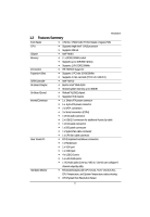
(PCI-E x1/ USB 2.0) Intel® NM 10 Build in Intel® GMA 3150 Shared system memory up to 384MB Relteak®ALC662 chipset Supports HD 6 channel 1 x 24-pin ATX power connector 1 x 4-pin ATX power connector 2 x SATA connectors 3 x Serial connectors (COM) 1 x front audio connector 2 x USB - Gigabyte MNNM1PI | Manual - Page 7
MNNM1PI Motherboard On-Board LAN BIOS Additional Features CPU shutdown when overheat Realtek 8111DL GbE LAN controller Supports WOL, PXE AMI BIOS on 8Mb SPI Flash ROM External Modem wake up Supports S1, S3, S4, S5 under Windows Operating System Wake on LAN (WOL) Supports 4-pin Fan - Gigabyte MNNM1PI | Manual - Page 8
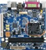
COMD SYS_FAN DIO 1.3 Motherboard Components Introduction PCI AUDIO USB_LAN R_USB ALC662 F_AUDIO VGA COMA KB LPT MS COMB MIN_CARD ITE IT8721F 8111DL ATX_12V COMC JP5 Intel F_USB1 NM10 F_USB2 CPU CPU_FAN BIOS BATTERY F_PANEL DDRII1 DDRII2 ATX 8 - Gigabyte MNNM1PI | Manual - Page 9
be installed in only one direction. If you are unable to insert the module, please switch the direction. The motherboard supports DDR2 memory module, whereby BIOS will automatically detect memory capacity and specifications. The memory module only can be inserted in one direction. Installation Steps - Gigabyte MNNM1PI | Manual - Page 10
MNNM1PI Motherboard 2-2: Connect ribbon cables, cabinet wires, and power supply 2-2-1 : I/O Back Panel Introduction 10 - Gigabyte MNNM1PI | Manual - Page 11
mouse, scanner, zip, speaker...etc. have a standard USB interface. Also make sure your OS supports USB controller. If your OS does not support USB controller, please contact OS vendor for possible patch or driver updated. For more information please contact your OS or device(s) vendors. LAN Port The - Gigabyte MNNM1PI | Manual - Page 12
MNNM1PI Motherboard LAN LED Description LED2 (Green/Orange) LED1 (Yellow) Name LED1 LED2 Color Green Green Green Green Yellow Yellow Condition ON BLINK OFF OFF OFF ON - Gigabyte MNNM1PI | Manual - Page 13
Connector Introduction 2-3: Connectors Introduction & Jumper Setting 11 12 2 5 10 9 6 7 8 3 4 13 14 16 17 15 1 1. ATX 2. ATX_12V 3. SATAII1 (SATA cable connector) 4. SATAII2 (SATA cable connector) 5. COMB 6. COMC 7. COMD 8. JP5 (COM Power Source jumper) 9. F_USB1 (Fornt USB cable - Gigabyte MNNM1PI | Manual - Page 14
Align the power connector with its proper location on the motherboard and connect tightly. The ATX_12V power connector mainly supplies power will not start. Caution! Please use a power supply that is able to support the system voltage requirements. It is recommended that a power supply that can - Gigabyte MNNM1PI | Manual - Page 15
MNNM1PI Motherboard 1 12 13 24 Pin No. 1 2 3 4 5 6 7 8 9 10 11 12 Definition cable connectors) SATA 3Gb/s can provide up to 300MB/s stransfer rate. Please refer to the BIOS setting for the SATA 3Gb/s and install the proper driver in order to work properly. 11 77 Pin No. 1 2 3 4 5 6 7 - Gigabyte MNNM1PI | Manual - Page 16
MNNM1PI Motherboard 5/6/7 ) COMB/COMC/COMD (Serial cable connectors) COMB COMC COMD COMB 2 10 19 Pin No. 1 2 3 4 5 6 7 8 9 10 Definition NDCDBNRXDB NTXDBNDTRB- GND NDSRBNRTSBNCTSBNRIB- NC COMC 12 COMD 12 9 - Gigabyte MNNM1PI | Manual - Page 17
MNNM1PI Motherboard 8 ) JP5 (Power COM selection jumper) 12 9 10 Pin No. 1 2 3 4 5 6 7 8 9 10 Definition IO_12V IO_12V COM_NRIC COM_NRID IO_VCC IO_VCC COM_NRIC COM_NRID NRICNRID- RI Default +5V +5V +12V - Gigabyte MNNM1PI | Manual - Page 18
MNNM1PI Motherboard 9/10 ) F_USB1/F_USB2 (Front USB cable connectors) Be careful with the on the cable is the same as the pin assigment on the MB header. To find out if the chassis you are buying support front audio connector, please contact your dealer. 2 10 19 Pin No. 1 2 3 4 5 6 7 8 9 10 - Gigabyte MNNM1PI | Manual - Page 19
12 ) DIO (Digtal I/O connector) Connector Introduction Pin No. Definition 12 1 2 VCC3 VCC3 3 VCC3 4 VCC3 78 5 ATX_3VSB 6 ATX_3VSB 7 ATX_3VSB 8 GND 13/14 ) CPU_FAN/SYS_FAN (CPU fan/System fan cable connectors) The cooler fan power connector supplies a +12V power voltage via a 3-pin - Gigabyte MNNM1PI | Manual - Page 20
15 ) F_Panel (2X5 Pins Front Panel connector) Connector Introduction Please connect the power LED, PC speaker, reset switch and power switch of your chassis front panel to the F_PANEL connector according to the pin assignment above. 2 10 1 9 Pin No. 1. 2. 3. 4. 5. 6. 7. 8. 9. 10. Signal - Gigabyte MNNM1PI | Manual - Page 21
MNNM1PI Motherboard 16 ) BATTERY If you want to erase CMOS... 1.Turn OFF the computer same or equivalent type recommended by the manufacturer. Dispose of used batteries according to the manufacturer's instructions. 17 ) CLR_CMOS (Clear CMOS jumper) You may clear the CMOS data to its default values - Gigabyte MNNM1PI | Manual - Page 22
Chapter 3 BIOS Setup MNNM1PI Motherboard BIOS (Basic Input and Output System) includes a CMOS SETUP utility which allows user to configure required settings or to activate certain system features. The CMOS SETUP saves the configuration in the CMOS SRAM of the motherboard. When the power is turned - Gigabyte MNNM1PI | Manual - Page 23
MNNM1PI Motherboard GETTINGHELP Main Menu The on-line description of the highlighted setup highlighted item. To exit the Help Window press . Select the Load Setup Defaults item in the BIOS Exit Setup menu when somehow the system is not stable as usual. This action makes the system reset to - Gigabyte MNNM1PI | Manual - Page 24
MNNM1PI Motherboard Main Once you enter AMI BIOS Setup Utility, the Main Menu will appear on the screen. Use arrow keys to select among the items and press to accept or enter the sub-menu. BIOS SETUP UTILITY Main Advanced PCIPnP Boot Security Chipset Exit System Overview AMI BIOS Version: - Gigabyte MNNM1PI | Manual - Page 25
MNNM1PI Motherboard Advanced About This Section: Advanced With this section, allowing user to , Hardware Health Configuration, ACPI Configuration, MPS Configuration, and USB Configuration. BIOS SETUP UTILITY Main Advanced PCIPnP Boot Security Chipset Exit Advanced Settings WARNING: Setting - Gigabyte MNNM1PI | Manual - Page 26
Configuration BIOS SETUP UTILITY Main Advanced PCIPnP Boot Security Chipset Exit CPU Configuration Module Version: 3F.15 MNNM1PI Motherboard Manufacturer: the computer is booted up, the operating system executes the CPUID instruction to identify the processor and its capabilities. Before it can do - Gigabyte MNNM1PI | Manual - Page 27
IDE Configuration BIOS SETUP UTILITY Main Advanced PCIPnP Boot Security Chipset Exit IDE Configuration Configure SATA as [IDE] Primary IDE Master Secondary IDE Master IDE Detect Time Out (Sec) [35] MNNM1PI Motherboard Select Screen Select Item +- Change Field Tab Select Field - Gigabyte MNNM1PI | Manual - Page 28
MNNM1PI Motherboard Auto: Set parameters automatically. (Default setting) CD-ROM: Use for ATAPI CD-ROM drives or double click [Auto] to set all HDD parameters automatically. ARMD: Use ARMD drive is installed here. LBA/Large Mode Configure the device type in the specific IDE channel support LBA Mode. - Gigabyte MNNM1PI | Manual - Page 29
MNNM1PI Motherboard 32Bit Data Transfer Configure the 32Bit Data Transfer rate. Enabled: Enable 32Bit Data Transfer rate. Disabled: 32Bit Data Transfer rate. Auto: Auto configuration. (Default setting) - Gigabyte MNNM1PI | Manual - Page 30
Super IO Configuration BIOS SETUP UTILITY Main Advanced PCIPnP Boot Security Chipset Exit Configure ITE8721 Super IO Chipset MNNM1PI Motherboard Serial Port1 Address Serial Port2 Address Parallel Port Address Parallel Port Mode Parallel Port IRQ Eup lot6 Serial Port3 Address Serial Port4 Address - Gigabyte MNNM1PI | Manual - Page 31
MNNM1PI Motherboard Parallel Port Address 378 Enable parallel port and set IO address to 378. (Default setting) 278 Enable parallel port and set IO address to 278. - Gigabyte MNNM1PI | Manual - Page 32
Disabled Disable Serial Port 3/4. MNNM1PI Motherboard Serial Port 3/4 IRQ IRQ3 Set IO address to IRQ3. IRQ4 Set IO address to IRQ4. IRQ9 Set IO address to IRQ9. IRQ10 Set IO address - Gigabyte MNNM1PI | Manual - Page 33
Hardware Health Configuration MNNM1PI Motherboard Default Screen BIOS SETUP UTILITY Main Advanced PCIPnP Boot American Megatrends, Inc. When CPU FAN Mode Setting is set to Automatic mode BIOS SETUP UTILITY Main Advanced PCIPnP Boot Security Chipset Exit Hardware Health Configuration CPU FAN - Gigabyte MNNM1PI | Manual - Page 34
MNNM1PI Motherboard When CPU FAN Mode Setting is set to PWM Manually mode BIOS SETUP UTILITY Main Advanced PCIPnP Boot Security Chipset Exit Hardware Health Configuration CPU FAN Stop Warning System FAN Stop Warning Hardware Health Function CPU FAN - Gigabyte MNNM1PI | Manual - Page 35
CPU FAN Start PWM Slope PWM of CPU FAN MNNM1PI Motherboard FAN start PWM value.User can define the limit value. Minimum PWM value is 0 MaximumPWM value is 255. The PWM value is subject to the temperature inputs by inear changing. PWM Manually Mode CPU FAN PWM Control PWM Duty Cycle control. - Gigabyte MNNM1PI | Manual - Page 36
ACPI Configuration BIOS SETUP UTILITY Main Advanced PCIPnP Boot Security Chipset Exit ACPI Settings Suspend Mode ACPI Version Features ACPI APIC support Resume On RTC Alarm epost Video on S3 Resume [Auto] [ACPI v3.0] [Enabled] [Disabled] [No] MNNM1PI Motherboard Select Screen Select Item - Gigabyte MNNM1PI | Manual - Page 37
MNNM1PI Motherboard Resume On RTC Alarm You can set "Resume by Alarm" item to enabled and key in Data/time to power on system. Disabled Disable this - Gigabyte MNNM1PI | Manual - Page 38
USB Configuration USB Configuration BIOS SETUP UTILITY Main Advanced PCIPnP Boot Security Chipset Exit USB Configuration MNNM1PI Motherboard Module Version USB Device Enabled: 1 Drive Legacy USB Support USB Keyboard Legacy Support USB Mouse Legacy Support USB Storage Device Support 2.24.3-13 - Gigabyte MNNM1PI | Manual - Page 39
MNNM1PI Motherboard Legacy USB Support Auto Auto detection. Enabled Enable Legacy USB device. (Default setting) Disabled Keep USB devices available only for EFI applications. USB Keyboard Legacy Support Enabled Enable USB Keyboard Legacy Support. (Default setting) Disabled Disable USB - Gigabyte MNNM1PI | Manual - Page 40
MNNM1PI Motherboard PCI/PnP BIOS SETUP UTILITY Main Advanced PCIPnP Boot Security Chipset Exit Advanced ) devices not required for boot if your system has a Plug and Play system. No Let the BIOS configure all the devices in the system. (Default setting) IRQ3/IRQ4/IRQ5/IRQ7/IRQ9/IRQ10/IRQ11/IRQ14 - Gigabyte MNNM1PI | Manual - Page 41
Settings Configuration Boot Device Priority MNNM1PI Motherboard Main Advanced Select Screen Select Item +- Change Field Tab Select Field F1 General Help F10 Save and Exit ESC Exit v02.61 (C) Copyright 1985-2006, American Megatrends, Inc. BIOS SETUP UTILITY PCIPnP Boot Security - Gigabyte MNNM1PI | Manual - Page 42
MNNM1PI Motherboard Quick Boot Enabled Allow BIOS to skip certain tests while booting. (Default setting) Priority This field determines which type of device the system attempt to boot from after BIOS Post completed. Specifies the boot sequence from the available devices. If the first device - Gigabyte MNNM1PI | Manual - Page 43
MNNM1PI Motherboard Security About This Section: Security In this section, user can set either supervisor or user passwords, or both for different level of password securities. In addition, user also can set the virus protection for boot sector. BIOS SETUP UTILITY Main Advanced PCIPnP Boot Security - Gigabyte MNNM1PI | Manual - Page 44
Full Access No Access Limited View Only MNNM1PI Motherboard Fully authorization for User accessing the setup utility.. (Default setting) Prevents User access to the setup utility. Allows only limited fields to be changed such - Gigabyte MNNM1PI | Manual - Page 45
Chipset BIOS SETUP UTILITY Main Advanced PCIPnP Boot Security Chipset Exit Advanced Chipset Settings North Bridge Configuration South Bridge Configuration Onboard Peripherals Configuration MNNM1PI Motherboard Select Screen Select Item +- Change Field Tab Select Field F1 General - Gigabyte MNNM1PI | Manual - Page 46
North Bridge Configuration BIOS SETUP UTILITY Main Advanced PCIPnP Boot Security Chipset Exit North Bridge Chipset Configuration Internal Graphics Mode Select DVMT Mode Select DVMT/FIXED Memory [Enabled, 8MB] [DVMT Mode] [256MB] MNNM1PI Motherboard Select Screen Select Item +- Change - Gigabyte MNNM1PI | Manual - Page 47
South Bridge Configuration BIOS SETUP UTILITY Main Advanced PCIPnP Boot Security Chipset Exit South Bridge Configuration HDA Controller Restore on AC Power Loss [Auto] [Power Off] MNNM1PI Motherboard Select Screen Select Item +- Change Field Tab Select Field F1 General Help F10 - Gigabyte MNNM1PI | Manual - Page 48
Onboard Peripheral Configuration BIOS SETUP UTILITY Main Advanced PCIPnP Boot Security Chipset Exit Onboard LAN Controller LAN Option ROM MAC Address : 00-E0-4C-68-00-12 [Enabled] [Disabled] MNNM1PI Motherboard Select Screen Select Item +- Change Field Tab Select Field F1 General - Gigabyte MNNM1PI | Manual - Page 49
Exit BIOS SETUP UTILITY Main Advanced PCIPnP Boot Security Chipset Exit Exit Options Save Changes and Exit Discard Changes and Exit Discard Changes Load Optimal Defaults MNNM1PI Motherboard Select Screen Select Item +- Change Field Tab Select Field F1 General Help F10 Save and Exit
-
 1
1 -
 2
2 -
 3
3 -
 4
4 -
 5
5 -
 6
6 -
 7
7 -
8
-
9
-
10
-
11
-
12
-
13
-
14
-
15
-
16
-
17
-
18
-
19
-
20
-
21
-
22
-
23
-
24
-
25
-
26
-
27
-
28
-
29
-
30
-
31
-
32
-
33
-
34
-
35
-
36
-
37
-
38
-
39
-
40
-
41
-
42
-
43
-
44
-
45
-
46
-
47
-
48
-
49
 |
 |

USER’S MANUAL
MNNM1PI
Intel
®
mini-ITX Motherboard
Intel
®
mini-ITX Motherboard
Rev. 1001
*
The WEEE marking on the product indicates this product must not be disposed of with
user's other household waste and must be handed over to a designated collection point
for the recycling of waste electrical and electronic equipment!!
*
The WEEE marking applies only in European Union's member states.