Harbor Freight Tools 62779 User Manual - Page 5
Safety, Setup, Operation, Maintenance
 |
View all Harbor Freight Tools 62779 manuals
Add to My Manuals
Save this manual to your list of manuals |
Page 5 highlights
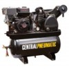
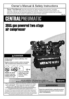
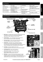
Safety Setup Specifications Pump Air Outlet Size Air Pressure Air Tank Capacity Air Flow Capacity Two stage 1/2″- NPT female Auto Shut-Off @ 180 PSI Restart @ 140 PSI 30 Gallons 18 CFM @ 90 PSI 19.5 CFM @ 40 PSI Oil Capacity Oil Type Required Rotation viewed from PTO (power takeoff - the output shaft) Required Engine Idle Speed 49 oz. (1.45L) SAE 30W non-detergent Air Compressor Oil (Item 95048, sold separately) Counterclockwise 2100 RPM ± 100 RPM Note: Engine specifications are found in the engine manual supplied with this equipment. Engine Controls Belt Guard Frame (122) & Belt Guard Cover (130) ON/OFF Switch Pilot Valve Pump Safety Valve (91) Air Filter Assembly (84) Tank Pressure Gauge (97) Oil Sight Glass (19) Tank Safety Valve (98) Air Outlet (106) Drain Valve (137) 1. Belt Guard - The Belt Guard encloses the pulleys and drive belts. It protects the user from the moving parts and allows the large pulley to direct cooling air to the Air Pump. Crankcase (16) 2. Oil Sight Glass - The oil sight glass shows proper level of the oil. Oil level should be at center of Sight Glass. 3. Tank Drain Valve - The Air Tank Drain Valve allows moisture to be removed from the tank to prevent corrosion. 4. Safety Valve - The Safety Valve automatically releases air if the Air Tank pressure exceeds the preset maximum. In an emergency, the ring can be pulled to relieve tank air pressure. There is one safety valve on the pump and one on the tank. Oil Sight Glass (19) OIL LEVEL OVERFILL FULL LOW 5. Air Outlet - An air hose attaches to this valve. Air pressure required by tools is set by an air pressure regulator. 6. Air Storage Tank - The Air Tank is where air pressurized by the Air Pump is stored for use. Opened Pilot Valve 7. Tank Pressure Gauge - The Air Tank Pressure Gauge displays the air pressure in the tank. 8. Pilot Valve - Open the Pilot Valve before starting the engine. It relieves resistance on the engine to make starting possible. Closed Pilot Valve Rotate the pin so it is vertical to open it. Once the engine is running, close the Pilot Valve so the Compressor can build up pressure. Operation Maintenance ITEM 62779 For technical questions, please call 1-888-866-5797. Page 5
-
 1
1 -
 2
2 -
 3
3 -
 4
4 -
 5
5 -
 6
6 -
 7
7 -
 8
8 -
 9
9 -
 10
10 -
 11
11 -
12
-
13
-
14
-
15
-
16
-
17
-
18
-
19
-
20
-
21
-
22
-
23
-
24
-
25
-
26
-
27
-
28
-
29
-
30
-
31
-
32
-
33
-
34
-
35
-
36
-
37
-
38
-
39
-
40
-
41
-
42
-
43
-
44
-
45
-
46
-
47
-
48
-
49
-
50
-
51
-
52
-
53
-
54
-
55
-
56
-
57
-
58
-
59
-
60
-
61
-
62
-
63
-
64
-
65
-
66
-
67
-
68
-
69
-
70
-
71
-
72
-
73
-
74
-
75
-
76
-
77
-
78
-
79
-
80
-
81
-
82
-
83
-
84
-
85
-
86
-
87
-
88
-
89
-
90
-
91
-
92
 |
 |
