Harbor Freight Tools 62779 User Manual - Page 6
Mounting to a Truck bed, Assembly, Break-In Compressor, Connection
 |
View all Harbor Freight Tools 62779 manuals
Add to My Manuals
Save this manual to your list of manuals |
Page 6 highlights
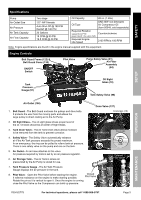
Safety Setup The emission control system for this Compressor's Engine is warranted for standards set by the U.S. Environmental Protection Agency and by the California Air Resources Board (also known as CARB). For warranty information, refer to the engine manual. Mounting to a Truck bed 1. Before mounting, if needed, reinforce the area with plywood or steel plating. 2. With assistance, move the compressor to the truck bed location and mark the floor of the truck bed through the holes in the compressor's feet. Check for any hidden wiring or cables and adjust the location for the holes as needed. Then, temporarily set the compressor aside. 3. Drill the four 1/2″ diameter holes through the truck bed and any reinforcing materials. 4. Set the compressor back in place, and align the foot holes with the pre-drilled holes. Use four 1/2″ diameter, bolts, washers and lock washers (all not included) to secure the compressor in place. Assembly Air Filter Second Stage Assembly (84) Cylinder Head Wing Nut (21) Connector First Stage Cylinder Head (61) To install the Air Filter Assembly (84), fit the Connector into the Air Filter Assembly and slide the assembly into the hole on the side of the First Stage Cylinder Head (61). Secure in place with the Wing Nut. Setup Operation Break-In Compressor Break in the new Air Compressor as follows: a. Make sure the engine is off. Open the air outlet valve on the left side of the tank. b. Check all fluid levels in the engine and pump. c. Start the engine following the General Operating Instructions. d. Let the unit run for 30 minutes. Air will expel freely through the Coupler. e. Turn OFF the engine. f. Remove the male coupler. Connection 1. Connect a regulator valve, an in-line shut off valve and a 1/2″ NPT air hose (all sold separately) to the Quick Coupler. The air hose must be long enough to reach the work area with enough extra length to allow free movement while working. Note: An in-line shutoff ball valve is an important safety device because it controls the air supply even if the air hose is ruptured. The shutoff valve should be a ball valve because it can be closed quickly. 2. Depending on the tool which you will be using with this compressor, you may need to incorporate additional components, such as an in-line oiler, a filter, or a dryer (all sold separately). Consult your air tool's manual for needed accessories. See Typical Air Line Setup charts on the following pages. This is a truckbed compressor, so use the portable setup as a model. Page 6 For technical questions, please call 1-888-866-5797. ITEM 62779 Maintenance
-
 1
1 -
 2
2 -
 3
3 -
 4
4 -
 5
5 -
 6
6 -
 7
7 -
 8
8 -
 9
9 -
 10
10 -
 11
11 -
 12
12 -
13
-
14
-
15
-
16
-
17
-
18
-
19
-
20
-
21
-
22
-
23
-
24
-
25
-
26
-
27
-
28
-
29
-
30
-
31
-
32
-
33
-
34
-
35
-
36
-
37
-
38
-
39
-
40
-
41
-
42
-
43
-
44
-
45
-
46
-
47
-
48
-
49
-
50
-
51
-
52
-
53
-
54
-
55
-
56
-
57
-
58
-
59
-
60
-
61
-
62
-
63
-
64
-
65
-
66
-
67
-
68
-
69
-
70
-
71
-
72
-
73
-
74
-
75
-
76
-
77
-
78
-
79
-
80
-
81
-
82
-
83
-
84
-
85
-
86
-
87
-
88
-
89
-
90
-
91
-
92
 |
 |
