Harman Kardon AVR 354 Owners Manual - Page 12
Coaxial 1/2 and Optical 1/2/3 Digital Audio Inputs - avr 354 protected mode
 |
View all Harman Kardon AVR 354 manuals
Add to My Manuals
Save this manual to your list of manuals |
Page 12 highlights
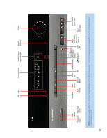
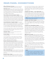
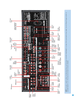
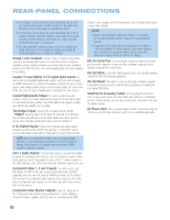
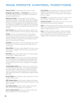
REAR-PANEL CONNECTIONS • The Analog 1 and 2 connectors don't physically line up with any analog video inputs. Consider using them for audio-only devices, such as a CD player or cassette tape deck. • The Analog 2 and 4 inputs are each associated with a set of outputs. Consider using the Analog 2 connectors for an audio recorder, and the Analog 4 connectors for a video recorder (along with the Video 2 connectors). • You may optionally connect a source to both an analog and digital audio input. This is useful for making recordings, for multizone applications or simply as a backup. Analog 2 and 4 Outputs: Connect either of these analog audio outputs to the analog audio inputs of a recording device. A signal is available at these outputs whenever an analog audio source is playing. However, the AVR 354 does not convert digital audio sources to analog for recording. Coaxial 1/2 and Optical 1/2/3 Digital Audio Inputs: If a source has a compatible digital audio output, and if you are not using an HDMI connection for audio for the device, connect it to one of these jacks to hear digital audio formats, such as Dolby Digital, DTS and linear PCM. Use only one type of digital audio connection for each source. Coaxial Digital Audio Output: If a source is also an audio recorder, connect a coaxial digital audio output to the recorder's input for improved recording quality. Only PCM digital audio signals (coaxial and optical) are available for recording. The Bridge II Input: Connect the included Harman Kardon docking station to this input for use with most docking iPod models, 4G and later (not included). Make sure the receiver is turned off (in Standby mode) when connecting The Bridge II. 6-/8-Channel Inputs: Connect the multichannel analog audio outputs of a DVD-Audio, SACD™, Blu-ray Disc™ or HD-DVD™ player (or any other external decoder) to these jacks to enjoy these formats. NOTE: When the multichannel player has an onboard digital decoder, it is not necessary to connect it to the 6-/8-Channel Analog Audio Inputs. Only a digital audio connection (HDMI, coaxial or optical) is needed. Zone 2 Audio Outputs: Connect these jacks to an external amplifier to power the speakers in the remote zone of a multizone system. When these jacks are used, it is possible to have a full 7.1-channel system in the main listening room at the same time the multizone system is in use. Component Video 1, 2 and 3 Inputs: If a video source (e.g., DVD player or HDTV tuner) has analog component video (Y/Pb/Pr) capability, and if you are not using an HDMI connection for the device, then connect the component video outputs of the source to one of the sets of component video inputs. Do not make any other video connections to that source. Component Video Monitor Outputs: If you are using one of the Component Video Inputs and your television or video display is component-video-capable, and if you are not connecting the HDMI Output to your display, connect these jacks to the corresponding inputs on your video display. NOTES: • Due to copy-protection restrictions, there is no output at the Component Video Monitor Outputs for copy-protected sources. • Composite and S-video signals are upscaled to as high as 1080i and available at these outputs. If your video display's best connection is component video, it is the only video connection required from the AVR to the display. RS-232 Serial Port: This specialized connector may be used with your personal computer in case we offer a software upgrade for the receiver at some time in the future. RS-232 Mode: Leave this switch popped out in the Operate position unless the AVR 354 is being upgraded. RS-232 Reset: This switch is only used during a software upgrade. A standard processor reset is performed by pressing and holding the front-panel OK Button. Switched AC Accessory Outlet: You may plug the AC power cord of one source device into this outlet, and it will turn on whenever you turn on the receiver. Do not use a source that consumes more than 50 watts of power. AC Power Input: After you have made all other connections, plug the AC power cord into this receptacle and into an unswitched wall outlet. 12 112
-
 1
1 -
2
-
3
-
4
-
5
-
6
-
 7
7 -
 8
8 -
 9
9 -
 10
10 -
 11
11 -
 12
12 -
 13
13 -
 14
14 -
 15
15 -
 16
16 -
 17
17 -
18
-
19
-
20
-
21
-
22
-
23
-
24
-
25
-
26
-
27
-
28
-
29
-
30
-
31
-
32
-
33
-
34
-
35
-
36
-
37
-
38
-
39
-
40
-
41
-
42
-
43
-
44
-
45
-
46
-
47
-
48
-
49
-
50
-
51
-
52
-
53
-
54
-
55
-
56
-
57
-
58
-
59
-
60
-
61
-
62
-
63
-
64
-
65
-
66
-
67
-
68
-
69
-
70
-
71
-
72
-
73
-
74
-
75
-
76
 |
 |
