Harman Kardon AVR 354 Owners Manual - Page 30
Step Six - Plug in AC Power, Step Seven - Insert Batteries in Remote
 |
View all Harman Kardon AVR 354 manuals
Add to My Manuals
Save this manual to your list of manuals |
Page 30 highlights
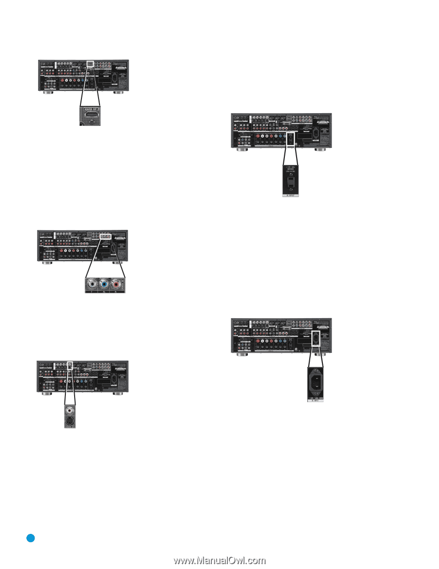
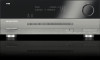
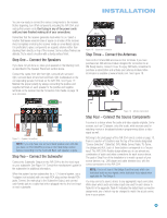
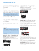
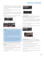
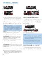
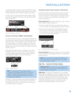
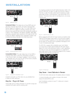
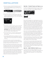
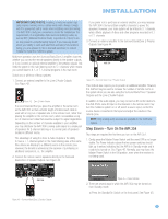
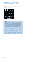
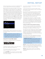
INSTALLATION AVR 354 You may plug one device into the AC Switched Accessory Outlet on the rear of the AVR 354. See Figure 35. Make sure this device draws no more than 50 watts. The device should have its mechanical or master power switch turned on, and it will power on any time the AVR 354 is turned on. If the device has a clock or must always be on, do not plug it into this outlet. Figure 32 - HDMI Monitor Output Component Video: If the display does not have HDMI inputs, but does have component video inputs, connect the Component Video Monitor Outputs to the display (see Figure 33). As with HDMI connections, the AVR 354 is capable of converting composite and S-video sources to the component video format, while upscaling the resolution to as high as 1080i, depending on the display's capabilities. Unlike HDMI connections, component video connections do not enable the AVR 354 to detect the display's capabilities and the appropriate resolution must be selected manually, as described in the Initial Setup section. AVR 354 Figure 33 - Component Video Monitor Outputs Composite/S-Video: If the video display does not have HDMI or component video inputs, connect the corresponding composite or S-video Monitor Output to the display. If available, S-video is preferred over composite video, and if used, the AVR 354 will convert composite video sources to S-video. See Figure 34. AVR 354 Figure 35 - Switched AC Accessory Outlet Before plugging the AVR 354's AC Power Cord into an electrical outlet, make sure that the Master Power Switch on the front panel is popped out so that the word OFF appears on its top. Gently press the button to turn the switch off. This will prevent the possibility of damaging the AVR in case of a transient power surge. The AVR 354 is equipped with a detachable power cord. It allows you to fully wire your system before installing the AVR, which may be required for some in-wall entertainment centers or custom applications. The male end of the cord should be plugged into an unswitched AC power outlet, and the female end should be plugged into the receptacle on the AVR 354's rear panel. See Figure 36. AVR 354 AVR 354 Figure 34 - Composite and S-Video Monitor Outputs Consult the manual for your TV to make sure you understand how to select the correct video input. Step Six - Plug in AC Power Having made all of your wiring connections, it is now time to plug each component's AC power cord into a working outlet. Figure 36 - AC Power Input Step Seven - Insert Batteries in Remote The AVR 354 remote control uses four AAA batteries, which are included. To remove the battery cover located on the back of the remote, squeeze the tab and lift the cover. Insert the batteries, as shown in Figure 37, making sure to observe the correct polarity. 30 30
-
 1
1 -
2
-
3
-
4
-
5
-
6
-
7
-
8
-
9
-
10
-
11
-
12
-
13
-
14
-
15
-
16
-
17
-
18
-
19
-
20
-
21
-
22
-
23
-
24
-
 25
25 -
 26
26 -
 27
27 -
 28
28 -
 29
29 -
 30
30 -
 31
31 -
 32
32 -
 33
33 -
 34
34 -
 35
35 -
36
-
37
-
38
-
39
-
40
-
41
-
42
-
43
-
44
-
45
-
46
-
47
-
48
-
49
-
50
-
51
-
52
-
53
-
54
-
55
-
56
-
57
-
58
-
59
-
60
-
61
-
62
-
63
-
64
-
65
-
66
-
67
-
68
-
69
-
70
-
71
-
72
-
73
-
74
-
75
-
76
 |
 |