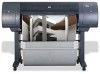
HP 4020 HP Designjet 4020 Printer series - Assembly Instructions: English - Page 7
tains the stand and the bin. Note: The brackets
 |
UPC - 884420909606
View all HP 4020 manuals
Add to My Manuals
Save this manual to your list of manuals |
Page 7 highlights
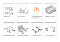
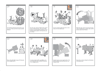
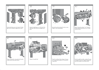
45 46 47 48 Remove the spindle lock foam piece. Then replace the spindle. 49 Remove the two brackets from the box that contains the stand and the bin. Note: The brackets are marked L and R. Use four screws to attach the brackets to the lower part of the printer legs. (Each bracket requires two screws.) 50 51 Attach the two plastic brackets to the top part of the printer legs. Insert the tab at the bottom of the bracket into the leg, and then 'click' the top of the bracket into place. 52 Remove the bin assembly from the box that contains the stand and the bin. Insert the two bin arms into the bin cross-bar. Insert the bin cross-bar into the two plastic brackets. Click the ends of both bin arms into the metal brackets.
-
 1
1 -
 2
2 -
 3
3 -
 4
4 -
 5
5 -
 6
6 -
 7
7 -
 8
8 -
 9
9 -
 10
10 -
 11
11 -
 12
12 -
13
-
14
-
15
-
16
-
17
-
18
 |
 |

49
50
51
52
Insert the bin cross-bar into the two plastic
brackets.
Remove the bin assembly from the box that
contains the stand and the bin.
Insert the two bin arms into the bin cross-bar.
Click the ends of both bin arms into the metal
brackets.
45
46
47
48
Use four screws to attach the brackets to the
lower part of the printer legs. (Each bracket
requires two screws.)
Remove the spindle lock foam piece. Then
replace the spindle.
Remove the two brackets from the box that con-
tains the stand and the bin. Note: The brackets
are marked L and R.
Attach the two plastic brackets to the top part of
the printer legs. Insert the tab at the bottom of
the bracket into the leg, and then ‘click’ the top
of the bracket into place.