HP 6125XLG HP 6125XLG Blade Switch Installation Guide
HP 6125XLG Manual
 |
View all HP 6125XLG manuals
Add to My Manuals
Save this manual to your list of manuals |
HP 6125XLG manual content summary:
- HP 6125XLG | HP 6125XLG Blade Switch Installation Guide - Page 1
HP 6125XLG Blade Switch Installation Guide Part number: 5998-3713 Document version: 6W101-20131112 - HP 6125XLG | HP 6125XLG Blade Switch Installation Guide - Page 2
, or use of this material. The only warranties for HP products and services are set forth in the express warranty statements accompanying such products and services. Nothing herein should be construed as constituting an additional warranty. HP shall not be liable for technical or editorial errors or - HP 6125XLG | HP 6125XLG Blade Switch Installation Guide - Page 3
member switches 13 Configuring basic IRF settings 13 Connecting the physical IRF ports 14 Accessing the IRF fabric to verify the configuration 14 Troubleshooting 15 Troubleshooting methods 15 Software failures 15 No terminal display 15 Garbled terminal display 15 Configuration problems 16 - HP 6125XLG | HP 6125XLG Blade Switch Installation Guide - Page 4
Console port 23 SFP+ port 24 QSFP+ port 25 Cables 26 Fiber connector 26 SFP+ cable 27 QSFP+ cable 27 QSFP+ to SFP+ cable 28 Index 29 ii - HP 6125XLG | HP 6125XLG Blade Switch Installation Guide - Page 5
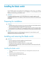
and Installation Guide. IMPORTANT: For regulatory identification purposes, the HP 6125XLG Blade Switch is assigned a regulatory model number (RMN) HSTNS-BC59-N. This regulatory number should not be confused with the marketing name HP 6125XLG. Preparing for installation WARNING! • The blade switches - HP 6125XLG | HP 6125XLG Blade Switch Installation Guide - Page 6
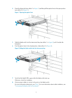
LED is green after the blade switch starts up. Otherwise, check the installation. 8. Choose proper cables to connect to the ports on the blade switch. For more information about ports, see "Ports." For more information about cable installation, see "Connecting the blade switch to the network." 2 - HP 6125XLG | HP 6125XLG Blade Switch Installation Guide - Page 7
the transceiver module, see Pluggable SFP[SFP+][XFP] Transceiver Modules Installation Guide and Pluggable QSFP+ Transceiver Modules/Cables Installation Guide. To install a transceiver module into the port on the blade switch and the peer device: 1. Remove the dust cover of the fiber connector - HP 6125XLG | HP 6125XLG Blade Switch Installation Guide - Page 8
. For more information about LED status, see "LEDs." After you connect the blade switch to the network, use the ping or tracert command to test network connectivity. For more information about these two commands, see HP 6125XLG Blade Switch Network Management and Monitoring Command Reference. 4 - HP 6125XLG | HP 6125XLG Blade Switch Installation Guide - Page 9
slot number of the blade switch. 6. Press Enter. When the command line prompt appears, you can configure the switch. For more information about the configuration, see "Configuring the blade switch." Logging in through the console port When you access the blade switch through the console port, you - HP 6125XLG | HP 6125XLG Blade Switch Installation Guide - Page 10
port to a terminal Setting terminal parameters To configure and manage the blade switch , you must run a terminal emulator program on the console terminal, for example, a PC. This section uses Windows XP HyperTerminal as an example. If you use Windows 7, download - HP 6125XLG | HP 6125XLG Blade Switch Installation Guide - Page 11
3. Select the serial port to be used from the Connect using list, and click OK. Figure 8 Setting the serial port used by the HyperTerminal connection 4. Set Bits per second to 9600, Data bits to 8, Parity to None, Stop bits to 1, and Flow control to None, and click OK, or click Restore Defaults. 7 - HP 6125XLG | HP 6125XLG Blade Switch Installation Guide - Page 12
Figure 9 Setting the serial port parameters 5. Select File > Properties in the HyperTerminal window. Figure 10 HyperTerminal window 6. On the Settings tab, set the emulation to VT100, and click OK. 8 - HP 6125XLG | HP 6125XLG Blade Switch Installation Guide - Page 13
You can configure authentication on a user interface to control access to the switch. Table 1 describes the Telnet login authentication methods available for a VTY user interface. For more information about login authentication methods, see HP 6125XLG Blade Switch Fundamentals Configuration Guide. 9 - HP 6125XLG | HP 6125XLG Blade Switch Installation Guide - Page 14
An HP 6125XLG blade switch without any configuration will continuously attempt to obtain an IP address via DHCP and then download a configuration file based on DHCP options 67 and 150. To use the auto-configuration feature, see HP 6125XLG Blade Switch Fundamentals Configuration Guide. The switch can - HP 6125XLG | HP 6125XLG Blade Switch Installation Guide - Page 15
address 192.168.0.1 24 [Sysname-Vlan-interface1] quit 2. Configure a static route: # Configure a static route, with the destination IP address 172.16.1.0 Sysname] ip route-static 172.16.1.0 255.255.255.0 192.168.0.2 3. Configure a VLAN: # Create VLAN 10 and enter its view. [Sysname] vlan 10 - HP 6125XLG | HP 6125XLG Blade Switch Installation Guide - Page 16
, see HP 6125XLG Blade Switch IRF Configuration Guide. Determine which switch you want to use as the master for managing all member switches in the IRF fabric. An IRF fabric has only one master switch. You configure and manage all member switches in the IRF fabric at the command line interface - HP 6125XLG | HP 6125XLG Blade Switch Installation Guide - Page 17
10. Configuring basic IRF settings After you install the IRF member blade switches, power on the blade switches, and log in to each IRF member blade switch (see HP 6125XLG Blade Switch Fundamentals Configuration Guide) to configure their member IDs, member priorities, and IRF port bindings. For - HP 6125XLG | HP 6125XLG Blade Switch Installation Guide - Page 18
fabric from the network management station. (See HP 6125XLG Blade Switch Fundamentals Configuration Guide.) 4. Verify that you can manage all member switches as if they were one node. 5. Display the running status of the IRF fabric by using the commands in Table 2. Table 2 Displaying and maintaining - HP 6125XLG | HP 6125XLG Blade Switch Installation Guide - Page 19
Enclosure Setup and Installation Guide. NOTE: If you cannot locate failures by following the guidelines in this chapter, contact HP Support. Software failures If the configuration environment setup is correct, the configuration terminal displays boot information when the blade switch is powered on - HP 6125XLG | HP 6125XLG Blade Switch Installation Guide - Page 20
Blade Switch Configuration Guides and HP 6125XLG Blade Switch Command References. Software upgrade failure HP recommends that you keep your software up-to-date. Periodically check the product webpage for available updates. To locate the software upgrade failure, verify that: 1. Physical ports - HP 6125XLG | HP 6125XLG Blade Switch Installation Guide - Page 21
enclosure, you can install the blade switch into it to check the operating state. 5. If the failure still exists, contact HP Support. Interface failure If the LED of an interface connected to the network is off, the interface or the connecting cable may fail. To troubleshoot the interface: 1. Verify - HP 6125XLG | HP 6125XLG Blade Switch Installation Guide - Page 22
Acronyms. Websites • HP.com http://www.hp.com • HP Networking http://www.hp.com/go/networking • HP manuals http://www.hp.com/support/manuals • HP download drivers and software http://www.hp.com/support/downloads • HP software depot http://www.software.hp.com • HP Education http://www.hp.com/learn 18 - HP 6125XLG | HP 6125XLG Blade Switch Installation Guide - Page 23
Command conventions Convention Boldface Italic [ ] { x | y | ... } [ x | y | ... ] { x | y | ... } * [ x | y | ... ] * & # Description Bold text represents commands bold text. For example, the New User window appears; click OK. Multi-level or damage to hardware or software. An alert that calls - HP 6125XLG | HP 6125XLG Blade Switch Installation Guide - Page 24
wired-WLAN switch. Represents an access point. Represents a security product, such as a firewall, a UTM, or a load-balancing or security card that is installed in a device. Represents a security card, such as a firewall card, a load-balancing card, or a NetStream card. Port numbering in examples - HP 6125XLG | HP 6125XLG Blade Switch Installation Guide - Page 25
-GE port, connecting to the server blade Ethernet ports Internal cross connect port (on the rear panel) External upstream ports (on the front panel) 4 × 10-GE port, connecting to the adjacent blade switch • 4 × QSFP+ port, connecting to network devices or other blade switches to form an IRF fabric - HP 6125XLG | HP 6125XLG Blade Switch Installation Guide - Page 26
(5) Release tab (7) Reset button (9) Port LED (6) SFP+ port (8) Console port NOTE: The Reset button is recessed in the device. To push the Reset button, use a thin, elongated object, such as a pencil. 22 - HP 6125XLG | HP 6125XLG Blade Switch Installation Guide - Page 27
present on the port. Ports Console port Every HP 6125XLG blade switch has one console port on its front panel. Table 5 Console port specifications Item Connector type Compliant standard Transmission baud rate Services Specification RJ-45 EIA/TIA-232 9600 bps (default) to 115200 bps • Provides - HP 6125XLG | HP 6125XLG Blade Switch Installation Guide - Page 28
SFP+ port An HP 6125XLG has eight SFP+ ports. They accept supported SFP transceiver modules, SFP+ modules, or SFP+ cables. Table 6 1000 Mbps SFP transceiver modules Product code Module description Central Fiber wavelength diameter (nm) (μm) JD118B HP X120 1G SFP LC SX Transceiver 850 50/ - HP 6125XLG | HP 6125XLG Blade Switch Installation Guide - Page 29
the transceiver module and cable specifications, see Pluggable SFP[SFP+][XFP] Transceiver Modules Installation Guide. QSFP+ port The HP 6125XLG supports QSFP+ modules and QSFP+ cables on the QSFP+ ports. Table 9 QSFP+ transceiver modules Product Code Module description Central wavelength Fiber - HP 6125XLG | HP 6125XLG Blade Switch Installation Guide - Page 30
blade switch are subject to change over time. For the most up-to-date list of transceiver modules and cables, consult your HP sales representative or technical support engineer. • For the transceiver module and cable specifications, see Pluggable QSFP+ Transceiver Modules/Cables Installation Guide - HP 6125XLG | HP 6125XLG Blade Switch Installation Guide - Page 31
Figure 16 MPO connector Figure 17 LC connector SFP+ cable You can use SFP+ cables to connect the SFP+ ports. The SFP+ cables available for the switch series are 10 G SFP+ Cu cables, as shown in Figure 18. Figure 18 SFP+ cable (1) Connector (2) Pull latch QSFP+ cable You can use QSFP+ cables - HP 6125XLG | HP 6125XLG Blade Switch Installation Guide - Page 32
Figure 19 QSFP+ cable (1) Connector (2) Pull latch QSFP+ to SFP+ cable A QSFP+ to SFP+ cable is a cable with one QSFP+ module at one end and four SFP+ modules at the other end. Figure 20 QSFP+ to SFP+ cable (1) QSFP+ connector (3) SFP+ connector (2) QSFP+ pull latch (4) SFP+ pull latch 28 - HP 6125XLG | HP 6125XLG Blade Switch Installation Guide - Page 33
,14 C Cables,26 Configuring basic IRF settings,13 Configuring the blade switch,9 Connecting the blade switch to the network,3 Connecting the physical IRF ports,14 Contacting HP,18 Conventions,19 F Front view,21 H Hardware failures,16 I Installing and removing the blade switch,1 Interface failure,17
-
 1
1 -
 2
2 -
 3
3 -
 4
4 -
 5
5 -
 6
6 -
 7
7 -
8
-
9
-
10
-
11
-
12
-
13
-
14
-
15
-
16
-
17
-
18
-
19
-
20
-
21
-
22
-
23
-
24
-
25
-
26
-
27
-
28
-
29
-
30
-
31
-
32
-
33
 |
 |

HP 6125XLG Blade Switch
Installation Guide
Part number: 5998-3713
Document version: 6W101-20131112