HP 6125XLG HP 6125XLG Blade Switch Installation Guide - Page 8
HP 6125XLG Blade Switch Network, Management and Monitoring Command Reference - blade switch command references
 |
View all HP 6125XLG manuals
Add to My Manuals
Save this manual to your list of manuals |
Page 8 highlights
Figure 3 Using LC optical fiber connectors to connect transceiver modules LC plug SFP module Figure 4 Using MPO optical fiber connectors to connect transceiver modules MPO plug QSFP+ module 3. Verify the port LEDs for correct connection. For more information about LED status, see "LEDs." After you connect the blade switch to the network, use the ping or tracert command to test network connectivity. For more information about these two commands, see HP 6125XLG Blade Switch Network Management and Monitoring Command Reference. 4
-
 1
1 -
2
-
 3
3 -
 4
4 -
 5
5 -
 6
6 -
 7
7 -
 8
8 -
 9
9 -
 10
10 -
 11
11 -
 12
12 -
 13
13 -
14
-
15
-
16
-
17
-
18
-
19
-
20
-
21
-
22
-
23
-
24
-
25
-
26
-
27
-
28
-
29
-
30
-
31
-
32
-
33
 |
 |
4
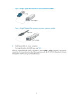
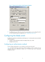
Figure 3
Using LC optical fiber connectors to connect transceiver modules
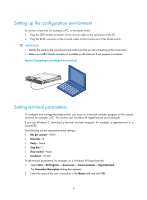
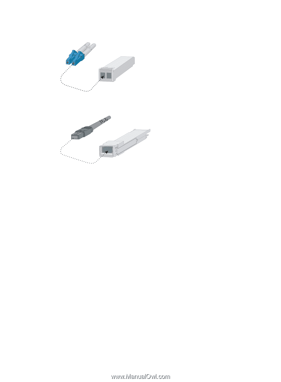
Figure 4
Using MPO optical fiber connectors to connect transceiver modules
3.
Verify the port LEDs for correct connection.
For more information about LED status, see "
LEDs
."
After you connect the blade switch to the network, use the
ping
or
tracert
command to test network
connectivity. For more information about these two commands, see
HP 6125XLG Blade Switch Network
Management and Monitoring Command Reference
.
LC plug
SFP module
MPO plug
QSFP+ module