HP 6125XLG HP 6125XLG Blade Switch Installation Guide - Page 17
Configuring basic IRF settings
 |
View all HP 6125XLG manuals
Add to My Manuals
Save this manual to your list of manuals |
Page 17 highlights
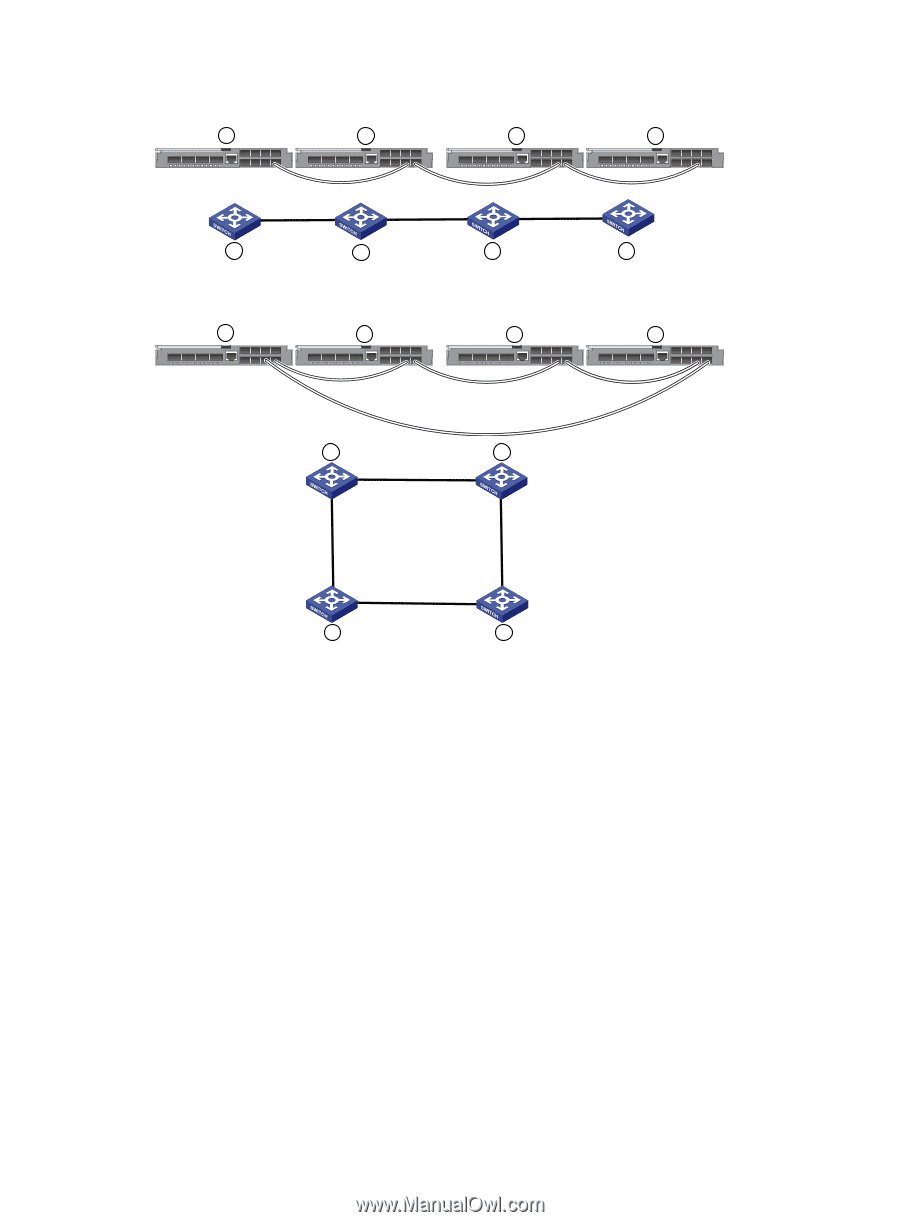
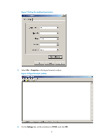
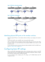
Figure 12 IRF fabric in daisy chain topology 1 2 3 4 IRF-port2 IRF-port2 IRF-port2 IRF-port1 IRF-port1 IRF-port1 1 2 3 4 Figure 13 IRF fabric in ring topology 1 2 3 4 1 IRF-port1 IRF-port2 IRF-port1 2 IRF-port2 IRF-port2 4 IRF-port2 IRF-port1 IRF-port1 3 Identifying physical IRF ports on the member switches Identify the physical IRF ports on the member switches according to your topology and connection scheme. On the switch, the SFP+ ports, and QSFP+ ports can be used for IRF connection. When two 6125XLG switches are plugged into adjacent (side-by-side) interconnect bays of the c7000, the internal 10-GE cross connect ports between those adjacent 6125XLG can be used for an IRF connection as well. For more information about the transceiver modules and cables available for the SFP+ and QSFP+ ports, see Table 7, Table 8, Table 9, and Table 10. Configuring basic IRF settings After you install the IRF member blade switches, power on the blade switches, and log in to each IRF member blade switch (see HP 6125XLG Blade Switch Fundamentals Configuration Guide) to configure their member IDs, member priorities, and IRF port bindings. For more information about configuring basic IRF settings, see HP 6125XLG Blade Switch IRF Configuration Guide. 13
-
 1
1 -
2
-
3
-
4
-
5
-
6
-
7
-
8
-
9
-
10
-
11
-
 12
12 -
 13
13 -
 14
14 -
 15
15 -
 16
16 -
 17
17 -
 18
18 -
 19
19 -
 20
20 -
 21
21 -
 22
22 -
23
-
24
-
25
-
26
-
27
-
28
-
29
-
30
-
31
-
32
-
33
 |
 |