HP 6125XLG HP 6125XLG Blade Switch Installation Guide - Page 30
Cables
 |
View all HP 6125XLG manuals
Add to My Manuals
Save this manual to your list of manuals |
Page 30 highlights
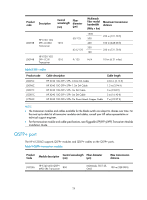
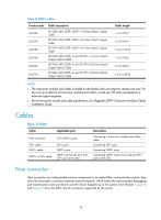
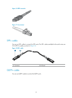
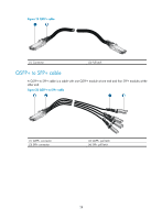
Table 10 QSFP+ cables Product code Cable description JG326A JG327A JG328A JG329A JG330A JG331A HP X240 40G QSFP+ QSFP+ 1m Direct Attach Copper Cable HP X240 40G QSFP+ QSFP+ 3m Direct Attach Copper Cable HP X240 40G QSFP+ QSFP+ 5m Direct Attach Copper Cable HP X240 40G QSFP+ to 4x10G SFP+ 1m Direct Attach Copper Splitter Cable HP X240 40G QSFP+ to 4x10G SFP+ 3m Direct Attach Copper Splitter Cable HP X240 40G QSFP+ to 4x10G SFP+ 5m Direct Attach Copper Splitter Cable Cable length 1 m (3.28 ft) 3 m (9.84 ft) 5 m (16.40 ft) 1 m (3.28 ft) 3 m (9.84 ft) 5 m (16.40 ft) NOTE: • The transceiver modules and cables available for the blade switch are subject to change over time. For the most up-to-date list of transceiver modules and cables, consult your HP sales representative or technical support engineer. • For the transceiver module and cable specifications, see Pluggable QSFP+ Transceiver Modules/Cables Installation Guide. Cables Figure 15 Cables Cable Applicable port Fiber connector SFP+ cable QSFP+ cable QSFP+ to SFP+ cable SFP+/QSFP+ ports SFP+ ports QSFP+ ports QSFP+ port at one end, and SFP+ port at the other Description Connecting a transceiver module and a fiber cable Connecting SFP+ ports Connecting QSFP+ ports Connecting QSFP+ ports at one end and SFP+ ports at the other Fiber connector Fiber connectors are indispensable passive components in an optical fiber communication system. They allow the removable connection between optical channels, which makes the optical system debugging and maintenance more convenient and the transit dispatching of the system more flexible. Figure 16 and Figure 17 show the MPO and LC connectors supported by the switch. 26
-
 1
1 -
2
-
3
-
4
-
5
-
6
-
7
-
8
-
9
-
10
-
11
-
12
-
13
-
14
-
15
-
16
-
17
-
18
-
19
-
20
-
21
-
22
-
23
-
24
-
 25
25 -
 26
26 -
 27
27 -
 28
28 -
 29
29 -
 30
30 -
 31
31 -
 32
32 -
 33
33
 |
 |