HP 6125XLG HP 6125XLG Blade Switch Installation Guide - Page 6
Opening the ejector lever, Sliding the blade switch into the interconnect bay
 |
View all HP 6125XLG manuals
Add to My Manuals
Save this manual to your list of manuals |
Page 6 highlights
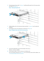
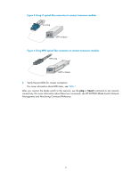
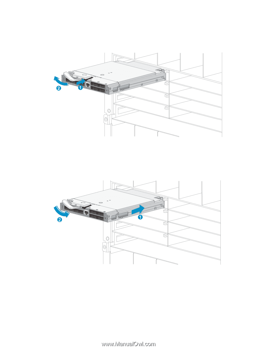
4. Press the release tab (see callout 1 in Figure 1) and then pull the ejector lever to the open position (see callout 2 in Figure 1). Figure 1 Opening the ejector lever 5. Slide the blade switch into the interconnect bay (see callout 1 in Figure 2) until it touches the backplane. 6. Push the ejector lever to the closed position. (See callout 2 in Figure 2). Figure 2 Sliding the blade switch into the interconnect bay 7. Verify that the Health LED is green after the blade switch starts up. Otherwise, check the installation. 8. Choose proper cables to connect to the ports on the blade switch. For more information about ports, see "Ports." For more information about cable installation, see "Connecting the blade switch to the network." 2
-
 1
1 -
 2
2 -
 3
3 -
 4
4 -
 5
5 -
 6
6 -
 7
7 -
 8
8 -
 9
9 -
 10
10 -
 11
11 -
 12
12 -
13
-
14
-
15
-
16
-
17
-
18
-
19
-
20
-
21
-
22
-
23
-
24
-
25
-
26
-
27
-
28
-
29
-
30
-
31
-
32
-
33
 |
 |
2
4.
Press the release tab (see callout 1 in
Figure 1
) and then pull the ejector lever to the open position
(see callout 2 in
Figure 1
).
Figure 1
Opening the ejector lever
5.
Slide the blade switch into the interconnect bay (see callout 1 in
Figure 2
) until it touches the
backplane.
6.
Push the ejector lever to the closed position. (See callout 2 in
Figure 2
).
Figure 2
Sliding the blade switch into the interconnect bay
7.
Verify that the Health LED is green after the blade switch starts up.
Otherwise, check the installation.
8.
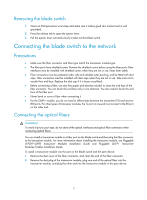
Choose proper cables to connect to the ports on the blade switch.
For more information about ports, see "
Ports
." For more information about cable installation, see
"
Connecting the blade switch to the network
."