HP 8530p HP EliteBook 8530p Notebook PC and HP EliteBook 8530w Mobile Workstat - Page 100
to remove them from the base, and frame and slide them to the right
 |
UPC - 884962209325
View all HP 8530p manuals
Add to My Manuals
Save this manual to your list of manuals |
Page 100 highlights
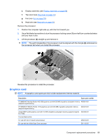
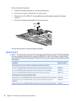
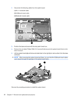
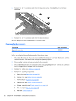
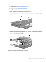
2. Disconnect the following cables from the system board: (1) RJ-11 connector cable (2) USB/audio board cable (3) Bluetooth module cable 3. Position the base enclosure with the rear panel toward you. 4. Remove the one black Phillips PM2.0×3.0 screw (1) that secures the system board frame to the base enclosure. 5. Lift the system board (2) and frame and slide them to the right (3) to remove them from the base enclosure. NOTE: When removing the system board and frame, be sure that the USB/audio board cables route cleanly through the openings in the system board frame. Reverse the preceding procedure to install the system board. 90 Chapter 4 Removal and replacement procedures
-
 1
1 -
2
-
3
-
4
-
5
-
6
-
7
-
8
-
9
-
10
-
11
-
12
-
13
-
14
-
15
-
16
-
17
-
18
-
19
-
20
-
21
-
22
-
23
-
24
-
25
-
26
-
27
-
28
-
29
-
30
-
31
-
32
-
33
-
34
-
35
-
36
-
37
-
38
-
39
-
40
-
41
-
42
-
43
-
44
-
45
-
46
-
47
-
48
-
49
-
50
-
51
-
52
-
53
-
54
-
55
-
56
-
57
-
58
-
59
-
60
-
61
-
62
-
63
-
64
-
65
-
66
-
67
-
68
-
69
-
70
-
71
-
72
-
73
-
74
-
75
-
76
-
77
-
78
-
79
-
80
-
81
-
82
-
83
-
84
-
85
-
86
-
87
-
88
-
89
-
90
-
91
-
92
-
93
-
94
-
 95
95 -
 96
96 -
 97
97 -
 98
98 -
 99
99 -
 100
100 -
 101
101 -
 102
102 -
 103
103 -
 104
104 -
 105
105 -
106
-
107
-
108
-
109
-
110
-
111
-
112
-
113
-
114
-
115
-
116
-
117
-
118
-
119
-
120
-
121
-
122
-
123
-
124
-
125
-
126
-
127
-
128
-
129
-
130
-
131
-
132
-
133
-
134
-
135
-
136
-
137
-
138
-
139
-
140
-
141
-
142
-
143
-
144
-
145
-
146
-
147
-
148
-
149
-
150
-
151
-
152
-
153
-
154
-
155
-
156
-
157
-
158
-
159
-
160
-
161
-
162
-
163
-
164
-
165
-
166
-
167
-
168
-
169
-
170
 |
 |

2.
Disconnect the following cables from the system board:
(1)
RJ-11 connector cable
(2)
USB/audio board cable
(3)
Bluetooth module cable
3.
Position the base enclosure with the rear panel toward you.
4.
Remove the one black Phillips PM2.0×3.0 screw
(1)
that secures the system board frame to the
base enclosure.
5.
Lift the system board
(2)
and frame and slide them to the right
(3)
to remove them from the base
enclosure.
NOTE:
When removing the system board and frame, be sure that the USB/audio board cables
route cleanly through the openings in the system board frame.
Reverse the preceding procedure to install the system board.
90
Chapter 4
Removal and replacement procedures