HP 8530p HP EliteBook 8530p Notebook PC and HP EliteBook 8530w Mobile Workstat - Page 85
Remove the four Torx T8M2.5×8.0 screws
 |
UPC - 884962209325
View all HP 8530p manuals
Add to My Manuals
Save this manual to your list of manuals |
Page 85 highlights
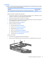
4. Remove the four Phillips PM 2.0x3.0 broadhead screws (3) 5. Turn the computer right-side up, with the rear toward you. 6. Remove the four Torx T8M2.5×8.0 screws (1) and the two HM2.5×6.0 screw locks (2) that secure the top cover to the computer. 7. Remove the microphone cable from the routing path in the top cover, and then disconnect the microphone cable from the system board. Component replacement procedures 75
-
 1
1 -
2
-
3
-
4
-
5
-
6
-
7
-
8
-
9
-
10
-
11
-
12
-
13
-
14
-
15
-
16
-
17
-
18
-
19
-
20
-
21
-
22
-
23
-
24
-
25
-
26
-
27
-
28
-
29
-
30
-
31
-
32
-
33
-
34
-
35
-
36
-
37
-
38
-
39
-
40
-
41
-
42
-
43
-
44
-
45
-
46
-
47
-
48
-
49
-
50
-
51
-
52
-
53
-
54
-
55
-
56
-
57
-
58
-
59
-
60
-
61
-
62
-
63
-
64
-
65
-
66
-
67
-
68
-
69
-
70
-
71
-
72
-
73
-
74
-
75
-
76
-
77
-
78
-
79
-
 80
80 -
 81
81 -
 82
82 -
 83
83 -
 84
84 -
 85
85 -
 86
86 -
 87
87 -
 88
88 -
 89
89 -
 90
90 -
91
-
92
-
93
-
94
-
95
-
96
-
97
-
98
-
99
-
100
-
101
-
102
-
103
-
104
-
105
-
106
-
107
-
108
-
109
-
110
-
111
-
112
-
113
-
114
-
115
-
116
-
117
-
118
-
119
-
120
-
121
-
122
-
123
-
124
-
125
-
126
-
127
-
128
-
129
-
130
-
131
-
132
-
133
-
134
-
135
-
136
-
137
-
138
-
139
-
140
-
141
-
142
-
143
-
144
-
145
-
146
-
147
-
148
-
149
-
150
-
151
-
152
-
153
-
154
-
155
-
156
-
157
-
158
-
159
-
160
-
161
-
162
-
163
-
164
-
165
-
166
-
167
-
168
-
169
-
170
 |
 |

4.
Remove the four Phillips PM 2.0x3.0 broadhead screws
(3)
5.
Turn the computer right-side up, with the rear toward you.
6.
Remove the four Torx T8M2.5×8.0 screws
(1)
and the two HM2.5×6.0 screw locks
(2)
that secure
the top cover to the computer.
7.
Remove the microphone cable from the routing path in the top cover, and then disconnect the
microphone cable from the system board.
Component replacement procedures
75