HP 8530p HP EliteBook 8530p Notebook PC and HP EliteBook 8530w Mobile Workstat - Page 89
Fan, Position the computer right-side up, with the front toward you. - elitebook base system device
 |
UPC - 884962209325
View all HP 8530p manuals
Add to My Manuals
Save this manual to your list of manuals |
Page 89 highlights
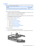
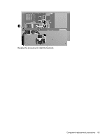
Fan Description For use with HP EliteBook 8530p computer models or HP EliteBook 8530w computer models For use with HP EliteBook 8530w computer models with Intel QX9300 Quad Core processor Spare part number 495079-001 495080-001 Before removing the fan, follow these steps: 1. Shut down the computer. If you are unsure whether the computer is off or in Hibernation, turn the computer on, and then shut it down through the operating system. 2. Disconnect all external devices connected to the computer. 3. Disconnect the power from the computer by first unplugging the power cord from the AC outlet and then unplugging the AC adapter from the computer. 4. Remove the battery (see Battery on page 44). 5. Remove the following components: a. Hard drive (see Hard drive on page 50) b. Optical drive (see Optical drive on page 46) c. Keyboard (see Keyboard on page 60) d. Switch cover (see Switch cover on page 65) e. Display assembly (see Display assembly on page 68) f. Top cover (see Top cover on page 74) Remove the fan: 1. Position the computer right-side up, with the front toward you. 2. Disconnect the fan cable (1) from the system board. 3. Remove the two Torx 8M2.5x7.0 screws (2) that secure the fan to the base enclosure. 4. Lift the front edge of the fan to remove it from (3) from the base enclosure. Component replacement procedures 79
-
 1
1 -
2
-
3
-
4
-
5
-
6
-
7
-
8
-
9
-
10
-
11
-
12
-
13
-
14
-
15
-
16
-
17
-
18
-
19
-
20
-
21
-
22
-
23
-
24
-
25
-
26
-
27
-
28
-
29
-
30
-
31
-
32
-
33
-
34
-
35
-
36
-
37
-
38
-
39
-
40
-
41
-
42
-
43
-
44
-
45
-
46
-
47
-
48
-
49
-
50
-
51
-
52
-
53
-
54
-
55
-
56
-
57
-
58
-
59
-
60
-
61
-
62
-
63
-
64
-
65
-
66
-
67
-
68
-
69
-
70
-
71
-
72
-
73
-
74
-
75
-
76
-
77
-
78
-
79
-
80
-
81
-
82
-
83
-
 84
84 -
 85
85 -
 86
86 -
 87
87 -
 88
88 -
 89
89 -
 90
90 -
 91
91 -
 92
92 -
 93
93 -
 94
94 -
95
-
96
-
97
-
98
-
99
-
100
-
101
-
102
-
103
-
104
-
105
-
106
-
107
-
108
-
109
-
110
-
111
-
112
-
113
-
114
-
115
-
116
-
117
-
118
-
119
-
120
-
121
-
122
-
123
-
124
-
125
-
126
-
127
-
128
-
129
-
130
-
131
-
132
-
133
-
134
-
135
-
136
-
137
-
138
-
139
-
140
-
141
-
142
-
143
-
144
-
145
-
146
-
147
-
148
-
149
-
150
-
151
-
152
-
153
-
154
-
155
-
156
-
157
-
158
-
159
-
160
-
161
-
162
-
163
-
164
-
165
-
166
-
167
-
168
-
169
-
170
 |
 |
