HP 8530p HP EliteBook 8530p Notebook PC and HP EliteBook 8530w Mobile Workstat - Page 101
RJ-11 connector cable, Top cover see
 |
UPC - 884962209325
View all HP 8530p manuals
Add to My Manuals
Save this manual to your list of manuals |
Page 101 highlights
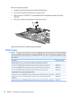
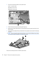
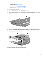
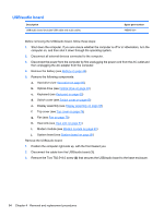
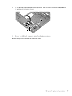
RJ-11 connector cable NOTE: The RJ-11 connector cable is included in the Cables Kit, spare part number 452198-001. Before removing the RJ-11 connector cable, follow these steps: 1. Shut down the computer. If you are unsure whether the computer is off or in Hibernation, turn the computer on, and then shut it down through the operating system. 2. Disconnect all external devices connected to the computer. 3. Disconnect the power from the computer by first unplugging the power cord from the AC outlet and then unplugging the AC adapter from the computer. 4. Remove the battery (see Battery on page 44). 5. Remove the following components: a. Hard drive (see Hard drive on page 50) b. Optical drive (see Optical drive on page 46) c. Keyboard (see Keyboard on page 60) d. Switch cover (see Switch cover on page 65) e. Display assembly (see Display assembly on page 68) f. Top cover (see Top cover on page 74) g. Fan (see Fan on page 79) h. Heat sink (see Heat sink on page 81) i. Modem module (see Modem module on page 63) j. System board (see System board on page 88) Remove the RJ-11 connector cable: 1. Position the computer right-side up, with the front toward you. 2. Remove the RJ-11 connector (1) from the clip built into the base enclosure. Component replacement procedures 91
-
 1
1 -
2
-
3
-
4
-
5
-
6
-
7
-
8
-
9
-
10
-
11
-
12
-
13
-
14
-
15
-
16
-
17
-
18
-
19
-
20
-
21
-
22
-
23
-
24
-
25
-
26
-
27
-
28
-
29
-
30
-
31
-
32
-
33
-
34
-
35
-
36
-
37
-
38
-
39
-
40
-
41
-
42
-
43
-
44
-
45
-
46
-
47
-
48
-
49
-
50
-
51
-
52
-
53
-
54
-
55
-
56
-
57
-
58
-
59
-
60
-
61
-
62
-
63
-
64
-
65
-
66
-
67
-
68
-
69
-
70
-
71
-
72
-
73
-
74
-
75
-
76
-
77
-
78
-
79
-
80
-
81
-
82
-
83
-
84
-
85
-
86
-
87
-
88
-
89
-
90
-
91
-
92
-
93
-
94
-
95
-
 96
96 -
 97
97 -
 98
98 -
 99
99 -
 100
100 -
 101
101 -
 102
102 -
 103
103 -
 104
104 -
 105
105 -
 106
106 -
107
-
108
-
109
-
110
-
111
-
112
-
113
-
114
-
115
-
116
-
117
-
118
-
119
-
120
-
121
-
122
-
123
-
124
-
125
-
126
-
127
-
128
-
129
-
130
-
131
-
132
-
133
-
134
-
135
-
136
-
137
-
138
-
139
-
140
-
141
-
142
-
143
-
144
-
145
-
146
-
147
-
148
-
149
-
150
-
151
-
152
-
153
-
154
-
155
-
156
-
157
-
158
-
159
-
160
-
161
-
162
-
163
-
164
-
165
-
166
-
167
-
168
-
169
-
170
 |
 |
