HP Chromebook 14-q000 Maintenance and Service Guide - Page 47
Aux/GPS terminal labeled 6., Remove the display assembly
 |
View all HP Chromebook 14-q000 manuals
Add to My Manuals
Save this manual to your list of manuals |
Page 47 highlights
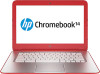
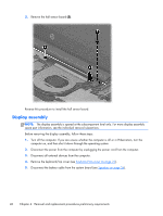
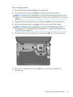
Remove the display assembly: 1. Disconnect the display panel cable (1) from the system board. 2. Disconnect the WLAN antenna cables (2) from the terminals on the WLAN module. NOTE: The WLAN antenna cable labeled "1" connects to the WLAN module "Main" terminal labeled "1". The WLAN antenna cable labeled "2" connects to the WLAN module "Aux" terminal labeled "2". 3. Release the WLAN antenna cables from the routing channel (3) built into the base enclosure. 4. Disconnect the WWAN antenna cables (4) from the terminals on the WWAN module. NOTE: The WWAN antenna cable labeled "5" connects to the WWAN module "Main" terminal labeled "5". The WWAN antenna cable labeled "6" connects to the WWAN module "Aux/GPS" terminal labeled "6". 5. Release the WWAN antenna cables from the routing channel (5) built into the base enclosure. 6. Remove the two Phillips PM2.5×5.5 screws (1) that secure the display assembly to the base enclosure. Component replacement procedures 41
-
 1
1 -
2
-
3
-
4
-
5
-
6
-
7
-
8
-
9
-
10
-
11
-
12
-
13
-
14
-
15
-
16
-
17
-
18
-
19
-
20
-
21
-
22
-
23
-
24
-
25
-
26
-
27
-
28
-
29
-
30
-
31
-
32
-
33
-
34
-
35
-
36
-
37
-
38
-
39
-
40
-
41
-
 42
42 -
 43
43 -
 44
44 -
 45
45 -
 46
46 -
 47
47 -
 48
48 -
 49
49 -
 50
50 -
 51
51 -
 52
52 -
53
-
54
-
55
-
56
-
57
-
58
-
59
-
60
-
61
-
62
-
63
-
64
-
65
-
66
-
67
-
68
-
69
-
70
 |
 |
