HP Cisco MDS 8/24c Cisco MDS 8Gb Fabric Switch for HP BladeSystem c-Class User - Page 8
Component identification, Port side of the switch, Internal ports summary, Switch redundancy
 |
View all HP Cisco MDS 8/24c manuals
Add to My Manuals
Save this manual to your list of manuals |
Page 8 highlights
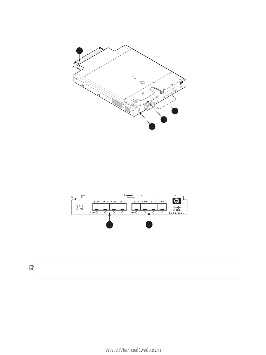
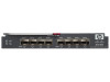
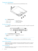
Component identification Figure 1 identifies the physical components of the Cisco MDS 8Gb Fabric Switch. 1 scale: 3/8" = 1" 196990 20 19 18 17 EXT 8 EXT 7 EXT 6 EXT5 Cisco MDS 8Gb Fabric Switch ! 2 3 4 Figure 1 Identifying components 1 Midplane connector 3 Installation handle 2 External SFP ports (Two populated, six unpopulated 4 UID and Health LEDs) Port side of the switch Figure 1 identifies Cisco MDS 8Gb Fabric Switch external ports (ports EXT 1 through EXT 4 and ports EXT 5 through EXT 8). 196996 1 2 Figure 2 Cisco MDS 8Gb Fabric Switch external ports 1 Left bank-EXT 1, EXT 2, EXT 3 and EXT 4 2 Right bank-EXT 5, EXT 6, EXT 7 and EXT 8 NOTE: See Interpreting LED activity for complete information on Cisco MDS 8Gb Fabric Switch LEDs. Internal ports summary Sixteen logical internal ports (numbered 1 through 16) connect sequentially to server bays 1 through 16 with the enclosure midplane. Server bay 1 is connected to Switch Port 1, Server bay 2 is connected to Switch port 2, and so forth. Switch redundancy The HP BladeSystem c-Class is engineered as a no-single-point-of-failure bladed solution. Attributes that contribute to switch redundancy include: 8 1 Overview
-
 1
1 -
2
-
 3
3 -
 4
4 -
 5
5 -
 6
6 -
 7
7 -
 8
8 -
 9
9 -
 10
10 -
 11
11 -
 12
12 -
 13
13 -
14
-
15
-
16
-
17
-
18
-
19
-
20
-
21
-
22
-
23
-
24
-
25
-
26
-
27
-
28
-
29
-
30
-
31
-
32
-
33
-
34
-
35
-
36
-
37
-
38
-
39
-
40
-
41
-
42
-
43
-
44
-
45
-
46
-
47
-
48
-
49
-
50
-
51
-
52
 |
 |