HP ENVY 13-ad000 Maintenance and Service Guide - Page 50
that secure the left and right I/O brackets to, keyboard/top cover.
 |
View all HP ENVY 13-ad000 manuals
Add to My Manuals
Save this manual to your list of manuals |
Page 50 highlights
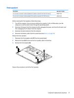
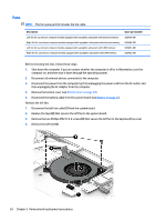
3. Release the adhesive support strip (3) that secures the display panel cable to the system board. 4. Release the ZIF connector (4) to which display panel cable is connected, and then disconnect the display panel cable from the system board. 5. Release the piece of tape (5) that secures the display panel cable to the system board. 6. Remove the two Phillips PM2.5×5.7 screws (1) that secure the left and right I/O brackets to the keyboard/top cover. 7. Remove the three Phillips PM2.0×2.0 broad head screws (2) that secure the left and right I/O brackets to the keyboard/top cover. 8. Remove the right I/O bracket (3). The right I/O bracket is available using spare part number 928468-001. 42 Chapter 5 Removal and replacement procedures
-
 1
1 -
2
-
3
-
4
-
5
-
6
-
7
-
8
-
9
-
10
-
11
-
12
-
13
-
14
-
15
-
16
-
17
-
18
-
19
-
20
-
21
-
22
-
23
-
24
-
25
-
26
-
27
-
28
-
29
-
30
-
31
-
32
-
33
-
34
-
35
-
36
-
37
-
38
-
39
-
40
-
41
-
42
-
43
-
44
-
 45
45 -
 46
46 -
 47
47 -
 48
48 -
 49
49 -
 50
50 -
 51
51 -
 52
52 -
 53
53 -
 54
54 -
 55
55 -
56
-
57
-
58
-
59
-
60
-
61
-
62
-
63
-
64
-
65
-
66
-
67
-
68
-
69
-
70
-
71
-
72
-
73
-
74
-
75
-
76
-
77
-
78
-
79
-
80
-
81
-
82
 |
 |

3.
Release the adhesive support strip
(3)
that secures the display panel cable to the system board.
4.
Release the ZIF connector
(4)
to which display panel cable is connected, and then disconnect the display
panel cable from the system board.
5.
Release the piece of tape
(5)
that secures the display panel cable to the system board.
6.
Remove the two Phillips PM2.5×5.7 screws
(1)
that secure the left and right I/O brackets to the
keyboard/top cover.
7.
Remove the three Phillips PM2.0×2.0 broad head screws
(2)
that secure the left and right I/O brackets to
the keyboard/top cover.
8.
Remove the right I/O bracket
(3)
.
The right I/O bracket is available using spare part number 928468-001.
42
Chapter 5
Removal and replacement procedures