HP ENVY 14-u000 ENVY 14 Notebook PC Maintenance and Service Guide - Page 51
Turn the computer over and open the display., Remove the three Phillips PM2.5×4.0 screws
 |
View all HP ENVY 14-u000 manuals
Add to My Manuals
Save this manual to your list of manuals |
Page 51 highlights
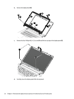
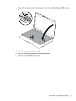
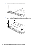
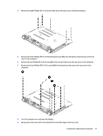
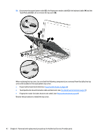
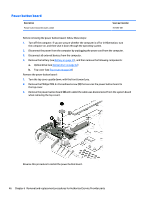
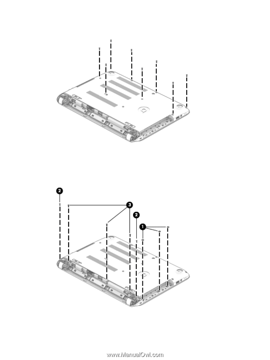
4. Remove the eight Phillips M2.5×4.0 screws that secure the top cover to the base enclosure. 5. Remove the three Phillips PM4.5×2.0 broad head screws (1) in the optical drive bay that secure the top cover to the computer. 6. Remove the two Phillips M2.5x4.0 screws (2) in the corners that secure the top cover to the computer. 7. Remove the three Phillips PM2.5×4.0 screws (3) in the battery bay that secure the top cover to the computer. 8. Turn the computer over and open the display. 9. Gently pull on the lower left corner (1) and lift around the edges of the top cover. Component replacement procedures 41
-
 1
1 -
2
-
3
-
4
-
5
-
6
-
7
-
8
-
9
-
10
-
11
-
12
-
13
-
14
-
15
-
16
-
17
-
18
-
19
-
20
-
21
-
22
-
23
-
24
-
25
-
26
-
27
-
28
-
29
-
30
-
31
-
32
-
33
-
34
-
35
-
36
-
37
-
38
-
39
-
40
-
41
-
42
-
43
-
44
-
45
-
 46
46 -
 47
47 -
 48
48 -
 49
49 -
 50
50 -
 51
51 -
 52
52 -
 53
53 -
 54
54 -
 55
55 -
 56
56 -
57
-
58
-
59
-
60
-
61
-
62
-
63
-
64
-
65
-
66
-
67
-
68
-
69
-
70
-
71
-
72
-
73
-
74
-
75
-
76
-
77
-
78
-
79
-
80
-
81
-
82
-
83
-
84
-
85
-
86
-
87
-
88
-
89
-
90
-
91
-
92
-
93
-
94
-
95
-
96
-
97
-
98
-
99
-
100
-
101
-
102
-
103
-
104
-
105
-
106
-
107
-
108
-
109
 |
 |
4.
Remove the eight Phillips M2.5×4.0 screws that secure the top cover to the base enclosure.
5.
Remove the three Phillips PM4.5×2.0 broad head screws
(1)
in the optical drive bay that secure the top
cover to the computer.
6.
Remove the two Phillips M2.5x4.0 screws
(2)
in the corners that secure the top cover to the computer.
7.
Remove the three Phillips PM2.5×4.0 screws
(3)
in the battery bay that secure the top cover to the
computer.
8.
Turn the computer over and open the display.
9.
Gently pull on the lower left corner
(1)
and lift around the edges of the top cover.
Component replacement procedures
41