HP ENVY 14-u000 ENVY 14 Notebook PC Maintenance and Service Guide - Page 70
Heat sink assembly, Turn the system board upside down, with the front toward you.
 |
View all HP ENVY 14-u000 manuals
Add to My Manuals
Save this manual to your list of manuals |
Page 70 highlights
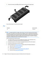
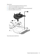
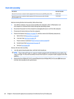
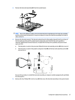
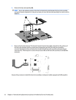
Heat sink assembly Description Heat sink for use only on computer models equipped with Intel processors and UMA graphics 19 W Heat sink for use only on computer models equipped with Intel processors and switchable discrete graphics 19 W Spare part number 763701-001 763703-001 Before removing the heat sink assembly, follow these steps: 1. Turn off the computer. If you are unsure whether the computer is off or in Hibernation, turn the computer on, and then shut it down through the operating system. 2. Disconnect the power from the computer by unplugging the power cord from the computer. 3. Disconnect all external devices from the computer. 4. Remove the battery (see Battery on page 31), and then remove the following components: a. Optical drive (see Optical drive on page 32) b. Top cover (see Top cover on page 39) c. Power connector cable (see Power connector cable on page 63) d. System board (see System board on page 52) e. Fan (see Fan on page 58) Remove the heat sink assembly: 1. Turn the system board upside down, with the front toward you. NOTE: Steps 2 through 4 apply to computer models equipped with switchable discrete graphics. See steps 5 through 7 for heat sink assembly removal information for computer models equipped with UMA graphics. 2. Remove the four Phillips M2.5x4.0 screws (1) and the three Phillips PM2.5x4.0 screws (2) that secure the heat sink assembly to the system board. 60 Chapter 6 Removal and replacement procedures for Authorized Service Provider parts
-
 1
1 -
2
-
3
-
4
-
5
-
6
-
7
-
8
-
9
-
10
-
11
-
12
-
13
-
14
-
15
-
16
-
17
-
18
-
19
-
20
-
21
-
22
-
23
-
24
-
25
-
26
-
27
-
28
-
29
-
30
-
31
-
32
-
33
-
34
-
35
-
36
-
37
-
38
-
39
-
40
-
41
-
42
-
43
-
44
-
45
-
46
-
47
-
48
-
49
-
50
-
51
-
52
-
53
-
54
-
55
-
56
-
57
-
58
-
59
-
60
-
61
-
62
-
63
-
64
-
 65
65 -
 66
66 -
 67
67 -
 68
68 -
 69
69 -
 70
70 -
 71
71 -
 72
72 -
 73
73 -
 74
74 -
 75
75 -
76
-
77
-
78
-
79
-
80
-
81
-
82
-
83
-
84
-
85
-
86
-
87
-
88
-
89
-
90
-
91
-
92
-
93
-
94
-
95
-
96
-
97
-
98
-
99
-
100
-
101
-
102
-
103
-
104
-
105
-
106
-
107
-
108
-
109
 |
 |