HP ENVY 14t-u000 HP ENVY 14 Notebook PC Maintenance and Service Guide - Page 43
Display subcomponents (bezel, webcamera, panel), and the two Phillips M2.5×3.0 screws
 |
View all HP ENVY 14t-u000 manuals
Add to My Manuals
Save this manual to your list of manuals |
Page 43 highlights
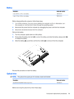
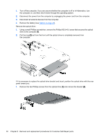
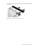
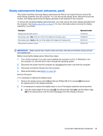
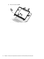
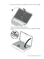
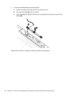
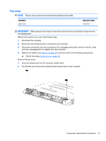
Display subcomponents (bezel, webcamera, panel) This section describes removing display subcomponents that do not require that you remove the entire display assembly from the computer. You can remove the display bezel, webcam/microphone module, and display panel while the display assembly is still attached to the computer. To remove the remaining display subcomponents, you must remove the entire display assembly from the computer. See Display assembly on page 61 for more information about removing the display assembly in its entirety. Description Display bezel (includes screws) Raw display panel, 14 in (35.56 cm), WLED, HD, BrightView flat display panel Raw display panel, 14.0 in (35.56 cm), FHD, WLED, SVA Antiglare slim display panel Webcamera/microphone module Spare part number 767365-001 763566-001 767373-001 762521-001 IMPORTANT: Make special note of each screw and screw lock size and location during removal and replacement Before removing the display panel, follow these steps: 1. Turn off the computer. If you are unsure whether the computer is off or in Hibernation, turn the computer on, and then shut it down through the operating system. 2. Disconnect the power from the computer by unplugging the power cord from the computer. 3. Disconnect all external devices from the computer. 4. Remove the battery (see Battery on page 29). Remove the panel: If it is necessary to replace the display bezel: 1. Remove the plastic screw covers (1) and the two Phillips M2.5×3.0 screws (2) that secure the display bezel to the display assembly. 2. If it is necessary to replace the display bezel or any of the display assembly subcomponents: a. Flex the inside edges of the top edge (3), the left and right sides (4), and the bottom edge (5) of the display bezel until the bezel disengages from the display enclosure. Component replacement procedures 33
-
 1
1 -
2
-
3
-
4
-
5
-
6
-
7
-
8
-
9
-
10
-
11
-
12
-
13
-
14
-
15
-
16
-
17
-
18
-
19
-
20
-
21
-
22
-
23
-
24
-
25
-
26
-
27
-
28
-
29
-
30
-
31
-
32
-
33
-
34
-
35
-
36
-
37
-
 38
38 -
 39
39 -
 40
40 -
 41
41 -
 42
42 -
 43
43 -
 44
44 -
 45
45 -
 46
46 -
 47
47 -
 48
48 -
49
-
50
-
51
-
52
-
53
-
54
-
55
-
56
-
57
-
58
-
59
-
60
-
61
-
62
-
63
-
64
-
65
-
66
-
67
-
68
-
69
-
70
-
71
-
72
-
73
-
74
-
75
-
76
-
77
-
78
-
79
-
80
-
81
-
82
-
83
-
84
-
85
-
86
-
87
-
88
-
89
-
90
-
91
-
92
-
93
-
94
-
95
-
96
-
97
 |
 |