HP ENVY 14t-u000 HP ENVY 14 Notebook PC Maintenance and Service Guide - Page 73
Remove the hinges, Remove the four bottom screws
 |
View all HP ENVY 14t-u000 manuals
Add to My Manuals
Save this manual to your list of manuals |
Page 73 highlights
b. Detach the webcamera/microphone module (2) from the display back cover. 2. If it is necessary to replace the hinges: a. Remove the two top screws (1) from the display hinges. b. Remove the four bottom screws (2) from the display hinges. c. Remove the hinges (3) from the display enclosure. 3. If it is necessary to replace the hinges on a touch panel: a. Remove the four top screws (1) from the display hinges. b. Remove the four bottom screws (2) from the display hinges. Component replacement procedures 63
-
 1
1 -
2
-
3
-
4
-
5
-
6
-
7
-
8
-
9
-
10
-
11
-
12
-
13
-
14
-
15
-
16
-
17
-
18
-
19
-
20
-
21
-
22
-
23
-
24
-
25
-
26
-
27
-
28
-
29
-
30
-
31
-
32
-
33
-
34
-
35
-
36
-
37
-
38
-
39
-
40
-
41
-
42
-
43
-
44
-
45
-
46
-
47
-
48
-
49
-
50
-
51
-
52
-
53
-
54
-
55
-
56
-
57
-
58
-
59
-
60
-
61
-
62
-
63
-
64
-
65
-
66
-
67
-
 68
68 -
 69
69 -
 70
70 -
 71
71 -
 72
72 -
 73
73 -
 74
74 -
 75
75 -
 76
76 -
 77
77 -
 78
78 -
79
-
80
-
81
-
82
-
83
-
84
-
85
-
86
-
87
-
88
-
89
-
90
-
91
-
92
-
93
-
94
-
95
-
96
-
97
 |
 |
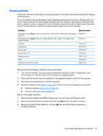
b.
Detach the webcamera/microphone module
(2)
from the display back cover.
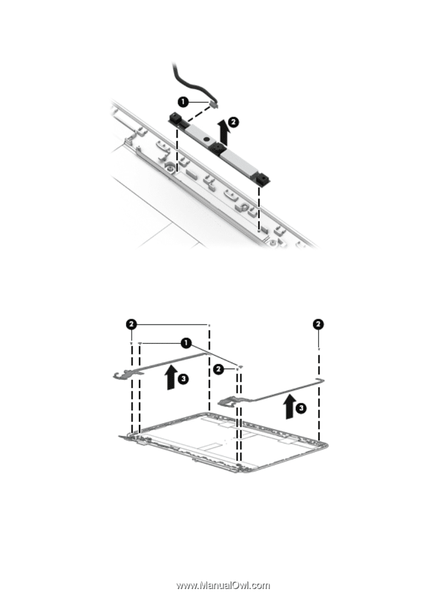
2.
If it is necessary to replace the hinges:
a.
Remove the two top screws
(1)
from the display hinges.
b.
Remove the four bottom screws
(2)
from the display hinges.
c.
Remove the hinges
(3)
from the display enclosure.
3.
If it is necessary to replace the hinges on a touch panel:
a.
Remove the four top screws
(1)
from the display hinges.
b.
Remove the four bottom screws
(2)
from the display hinges.
Component replacement procedures
63