HP ENVY 14t-u000 HP ENVY 14 Notebook PC Maintenance and Service Guide - Page 56
WLAN module, Optical drive see
 |
View all HP ENVY 14t-u000 manuals
Add to My Manuals
Save this manual to your list of manuals |
Page 56 highlights
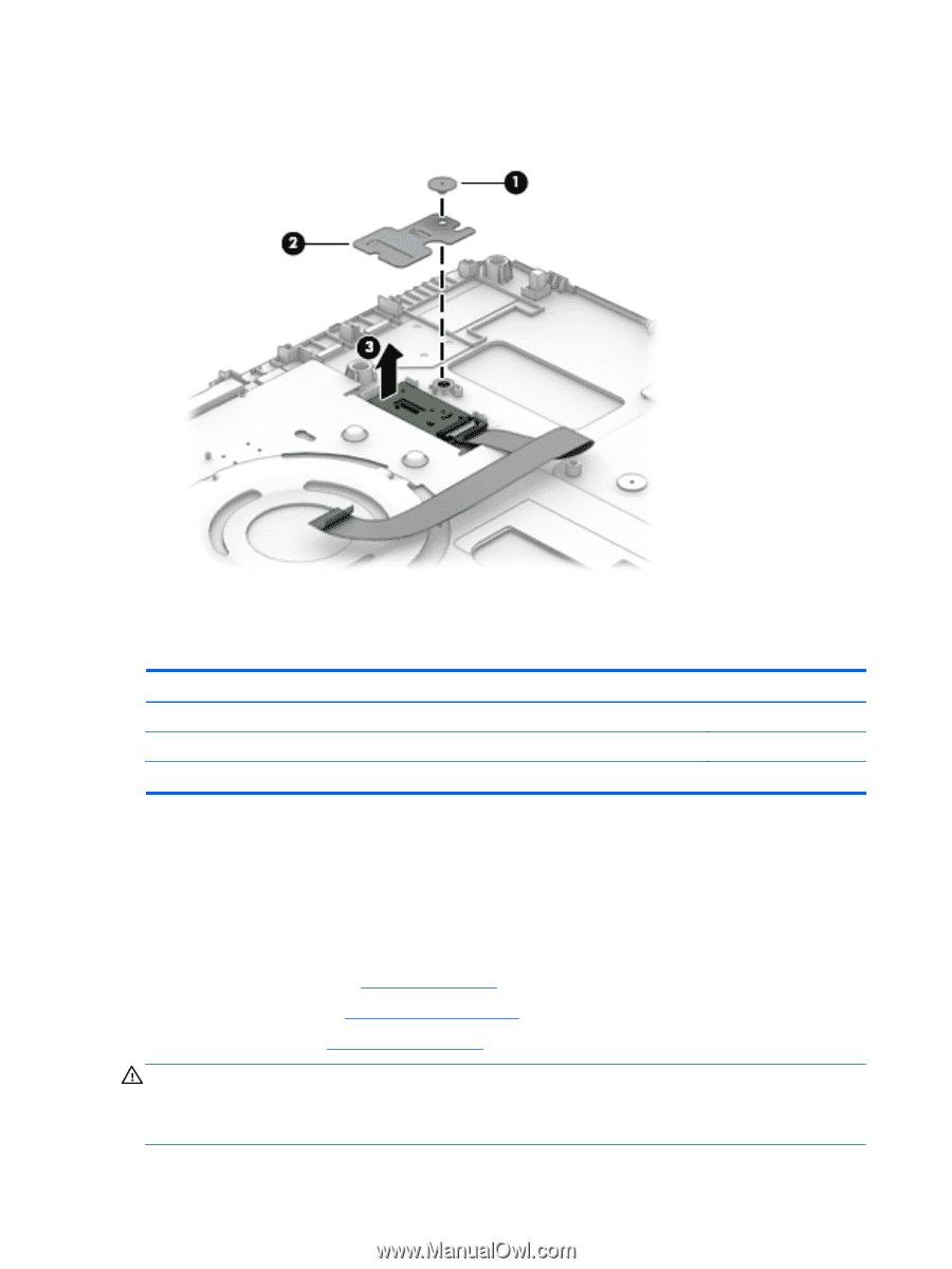
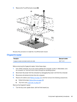
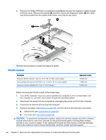
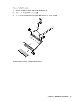
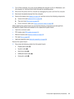
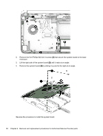
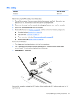
2. Remove the Phillips PM4.5x2.0 broadhead screw (1) that secures the fingerprint reader bracket to the top cover. Remove the bracket (2), and then remove the fingerprint reader (3) (the cable was disconnected from the system board when removing the top cover). Reverse this procedure to install the fingerprint reader. WLAN module Description Broadcom BCM43142 802.11 bgn 1x1 Wi-Fi + BT 4.0 HMC combo adapter Intel Dual Band Wireless-AC 3160 802.11 ac 1x1 WiFi + BT 4.0 combo adapter Qualcomm Atheros AR9485 802.11 bgn 1x1 Wi-Fi adapter Spare part number 753076-005 710662-005 675794-005 Before removing the WLAN module, follow these steps: 1. Turn off the computer. If you are unsure whether the computer is off or in Hibernation, turn the computer on, and then shut it down through the operating system. 2. Disconnect the power from the computer by unplugging the power cord from the computer. 3. Disconnect all external devices from the computer. 4. Remove the battery (see Battery on page 29), and then remove the following components: a. Optical drive (see Optical drive on page 29) b. Top cover (see Top cover on page 37) CAUTION: To prevent an unresponsive system, replace the wireless module only with a wireless module authorized for use in the computer by the governmental agency that regulates wireless devices in your country or region. If you replace the module and then receive a warning message, remove the module to restore device functionality, and then contact technical support. 46 Chapter 6 Removal and replacement procedures for Authorized Service Provider parts
-
 1
1 -
2
-
3
-
4
-
5
-
6
-
7
-
8
-
9
-
10
-
11
-
12
-
13
-
14
-
15
-
16
-
17
-
18
-
19
-
20
-
21
-
22
-
23
-
24
-
25
-
26
-
27
-
28
-
29
-
30
-
31
-
32
-
33
-
34
-
35
-
36
-
37
-
38
-
39
-
40
-
41
-
42
-
43
-
44
-
45
-
46
-
47
-
48
-
49
-
50
-
 51
51 -
 52
52 -
 53
53 -
 54
54 -
 55
55 -
 56
56 -
 57
57 -
 58
58 -
 59
59 -
 60
60 -
 61
61 -
62
-
63
-
64
-
65
-
66
-
67
-
68
-
69
-
70
-
71
-
72
-
73
-
74
-
75
-
76
-
77
-
78
-
79
-
80
-
81
-
82
-
83
-
84
-
85
-
86
-
87
-
88
-
89
-
90
-
91
-
92
-
93
-
94
-
95
-
96
-
97
 |
 |