HP ENVY 14t-u000 HP ENVY 14 Notebook PC Maintenance and Service Guide - Page 71
Display assembly, Disconnect the display cable
 |
View all HP ENVY 14t-u000 manuals
Add to My Manuals
Save this manual to your list of manuals |
Page 71 highlights
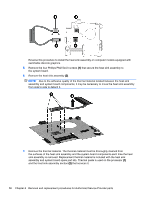
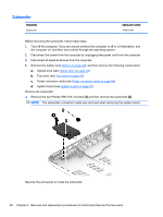
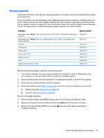
Display assembly This section describes removing the display assembly in its entirety and disassembling all the display subcomponents. If you only need to remove the display bezel, webcamera/microphone module, or display panel, you do not need to remove the entire display assembly from the computer. See Display subcomponents (bezel, webcam, panel) on page 34 for more information about removing the display subcomponents that do not require that you remove the entire display assembly from the computer. Description Raw display panel, 14.0 in (35.56 cm), high definition (HD), WLED, SVA BrightView flat display assembly Raw display panel, 14.0 in (35.56 cm), full high definition (FHD), WLED, SVA Antiglare slim display assembly Antennas Display bezel Display cable Display cable, FHD Display enclosure Hinge Webcamera/microphone module Spare part number 763566-001 767373-00 767237-001 767365-001 767244-001 767366-001 763751-001 767248-001 762521-001 Before removing the display assembly, follow these steps: 1. Turn off the computer. If you are unsure whether the computer is off or in Hibernation, turn the computer on, and then shut it down through the operating system. 2. Disconnect the power from the computer by unplugging the power cord from the computer. 3. Disconnect all external devices from the computer. 4. Remove the battery (see Battery on page 29), and then remove the following components: a. Optical drive (see Optical drive on page 29) b. Top cover (see Top cover on page 37) Remove the display assembly: 1. Disconnect the display cable (1) by flipping open the connector and lifting the cable. 2. Release the wireless antenna cables from the clips (2) built into the base enclosure. 3. Remove the three Phillips PM2.5×4.0 screws (3) that secure the display assembly to the base enclosure. Component replacement procedures 61
-
 1
1 -
2
-
3
-
4
-
5
-
6
-
7
-
8
-
9
-
10
-
11
-
12
-
13
-
14
-
15
-
16
-
17
-
18
-
19
-
20
-
21
-
22
-
23
-
24
-
25
-
26
-
27
-
28
-
29
-
30
-
31
-
32
-
33
-
34
-
35
-
36
-
37
-
38
-
39
-
40
-
41
-
42
-
43
-
44
-
45
-
46
-
47
-
48
-
49
-
50
-
51
-
52
-
53
-
54
-
55
-
56
-
57
-
58
-
59
-
60
-
61
-
62
-
63
-
64
-
65
-
 66
66 -
 67
67 -
 68
68 -
 69
69 -
 70
70 -
 71
71 -
 72
72 -
 73
73 -
 74
74 -
 75
75 -
 76
76 -
77
-
78
-
79
-
80
-
81
-
82
-
83
-
84
-
85
-
86
-
87
-
88
-
89
-
90
-
91
-
92
-
93
-
94
-
95
-
96
-
97
 |
 |