HP ENVY 14t-u000 HP ENVY 14 Notebook PC Maintenance and Service Guide - Page 65
Remove the thermal material. The thermal material must be thoroughly cleaned
 |
View all HP ENVY 14t-u000 manuals
Add to My Manuals
Save this manual to your list of manuals |
Page 65 highlights
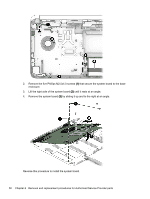
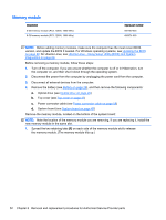
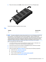
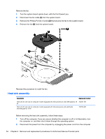
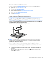
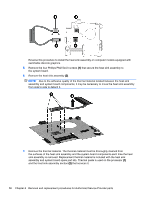
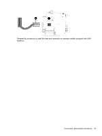
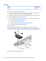
3. Disconnect all external devices from the computer. 4. Remove the battery (see Battery on page 29), and then remove the following components: a. Optical drive (see Optical drive on page 29) b. Top cover (see Top cover on page 37) c. Power connector cable (see Power connector cable on page 58) d. System board (see System board on page 48) e. Fan (see Fan on page 53) Remove the heat sink assembly: 1. Turn the system board upside down, with the front toward you. NOTE: Steps 2 through 4 apply to computer models equipped with switchable discrete graphics. See steps 5 through 7 for heat sink assembly removal information for computer models equipped with UMA graphics. 2. Remove the four Phillips M2.5x4.0 screws (1) and the three Phillips PM2.5x4.0 screws (2) that secure the heat sink assembly to the system board. 3. Remove the heat sink assembly (3) from the system board. NOTE: Due to the adhesive quality of the thermal material located between the heat sink assembly and the system board components, it may be necessary to move the heat sink assembly from side to side to detach it. 4. Remove the thermal material. The thermal material must be thoroughly cleaned from the surfaces of the heat sink assembly and the system board components each time the heat sink assembly is removed. Replacement thermal material is included with the heat sink assembly and system board spare part kits. ● Thermal paste is used on the processor (1) and the heat sink assembly section (2) that services it ● Thermal paste is used on the graphics subsystem chip (3) and the heat sink assembly section (4) that services it Component replacement procedures 55
-
 1
1 -
2
-
3
-
4
-
5
-
6
-
7
-
8
-
9
-
10
-
11
-
12
-
13
-
14
-
15
-
16
-
17
-
18
-
19
-
20
-
21
-
22
-
23
-
24
-
25
-
26
-
27
-
28
-
29
-
30
-
31
-
32
-
33
-
34
-
35
-
36
-
37
-
38
-
39
-
40
-
41
-
42
-
43
-
44
-
45
-
46
-
47
-
48
-
49
-
50
-
51
-
52
-
53
-
54
-
55
-
56
-
57
-
58
-
59
-
 60
60 -
 61
61 -
 62
62 -
 63
63 -
 64
64 -
 65
65 -
 66
66 -
 67
67 -
 68
68 -
 69
69 -
 70
70 -
71
-
72
-
73
-
74
-
75
-
76
-
77
-
78
-
79
-
80
-
81
-
82
-
83
-
84
-
85
-
86
-
87
-
88
-
89
-
90
-
91
-
92
-
93
-
94
-
95
-
96
-
97
 |
 |