HP ENVY 15-u010dx HP ENVY x360 Convertible PC Maintenance and Service Guide - Page 56
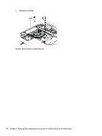
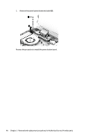
and then lift the left side of the, Flex the side of the computer so you can lift the heat sink out
 |
View all HP ENVY 15-u010dx manuals
Add to My Manuals
Save this manual to your list of manuals |
Page 56 highlights
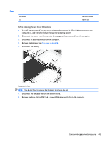
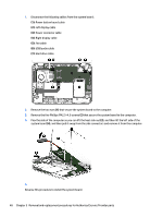
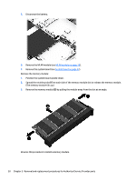
1. Disconnect the following cables from the system board: (1): Power button board cable (2): Left display cable (3): Power connector cable (4): Right display cable (5): Fan cable (6): USB/audio cable (7): Hard drive cable 2. Remove the two nuts (1) that secure the system board to the computer. 3. Remove the five Phillips PM2.5×4.0 screws (2) that secure the system board to the computer. 4. Flex the side of the computer so you can lift the heat sink out (3), and then lift the left side of the system board (4), and then pull it away from the side connectors and remove it from the computer. 5. Reverse this procedure to install the system board. 48 Chapter 5 Removal and replacement procedures for Authorized Service Provider parts
-
 1
1 -
2
-
3
-
4
-
5
-
6
-
7
-
8
-
9
-
10
-
11
-
12
-
13
-
14
-
15
-
16
-
17
-
18
-
19
-
20
-
21
-
22
-
23
-
24
-
25
-
26
-
27
-
28
-
29
-
30
-
31
-
32
-
33
-
34
-
35
-
36
-
37
-
38
-
39
-
40
-
41
-
42
-
43
-
44
-
45
-
46
-
47
-
48
-
49
-
50
-
 51
51 -
 52
52 -
 53
53 -
 54
54 -
 55
55 -
 56
56 -
 57
57 -
 58
58 -
 59
59 -
 60
60 -
 61
61 -
62
-
63
-
64
-
65
-
66
-
67
-
68
-
69
-
70
-
71
-
72
-
73
-
74
-
75
-
76
-
77
-
78
-
79
-
80
-
81
-
82
-
83
 |
 |

1.
Disconnect the following cables from the system board:
(1):
Power button board cable
(2):
Left display cable
(3):
Power connector cable
(4):
Right display cable
(5):
Fan cable
(6):
USB/audio cable
(7):
Hard drive cable
2.
Remove the two nuts
(1)
that secure the system board to the computer.
3.
Remove the five Phillips PM2.5×4.0 screws
(2)
that secure the system board to the computer.
4.
Flex the side of the computer so you can lift the heat sink out
(3)
, and then lift the left side of the
system board
(4)
, and then pull it away from the side connectors and remove it from the computer.
5.
Reverse this procedure to install the system board.
48
Chapter 5
Removal and replacement procedures for Authorized Service Provider parts